Tracking
A generic GNSS signal defined by its complex baseband equivalent, \(s_{T}(t)\), the digital signal at the input of a Tracking block can be written as:
\[\begin{equation} \label{xin} x_\text{IN}[k] = A(t)\tilde{s}_{T}(t - \tau(t))e^{j \left(2\pi f_D(t) t + \phi(t) \right)} \Bigr \rvert_{t=kT_s} + n(t) \Bigr \rvert_{t=kT_s}~, \end{equation}\]where \(A(t)\) is the signal amplitude, \(\tilde{s}_{T}(t)\) is a filtered version of \(s_T(t)\), \(\tau(t)\) is a time-varying code delay, \(f_D(t)\) is a time-varying Doppler shift, \(\phi(t)\) is a time-varying carrier phase shift, \(n(t)\) is a term modeling random noise and \(T_s\) is the sampling period.
The role of a Tracking block is to follow the evolution of the signal synchronization parameters: code phase \(\tau(t)\), Doppler shift \(f_D(t)\) and carrier phase \(\phi(t)\).
According to the Maximum Likelihood (ML) approach1, obtaining the optimum estimators implies the maximization of the correlation of the incoming signal with its matched filter. The ML estimates of \(f_D\) and \(\tau\) can be obtained by maximizing the function
\[\begin{equation} \hat{f}_{\!D_{ML}}, \hat{\tau}_{ML} = \arg \max_{f_D,\tau} \left\{ \left| \hat{R}_{xd}(f_D,\tau) \right|^2\right\}~, \end{equation}\]where
\[\begin{equation} \hat{R}_{xd}(f_D,\tau)= \frac{1}{K}\sum_{k=0}^{K-1}x_{\text{IN}}[k]d[kT_s - \tau]e^{-j 2 \pi f_D kT_s}~, \end{equation}\]with \(K\) being the number of samples in an integration period, and \(d[k]\) is a locally generated reference.
This is usually achieved with closed-loop structures designed to minimize the difference between the code phase, carrier phase, and frequency of the incoming signal with respect to the locally-generated replica \(d[k]\).
In the case of code phase tracking, the cost function is driven to the maximum using feedback loops that employ the derivative \(\frac{dR_{xd}(\tau)}{d\tau}\) zero-crossing as a timing error detector. This is the case of the Delay Lock Loop (DLL) architecture and its wide range of variants, where the receiver computes three samples of \(R_{xd}\), usually referred to as Early \(E=R_{xd}(\hat{\tau}+\epsilon)\), Prompt \(P=R_{xd}(\hat{\tau})\) and Late \(L=R_{xd}(\hat{\tau}-\epsilon)\), with \(\epsilon\) ranging from \(0.1T_c\) to \(0.5T_c\), and then computes a timing error with some combination of those samples, known as discriminator functions. The result is low-pass filtered and reinjected back to the matched filter, as shown in the figure below:
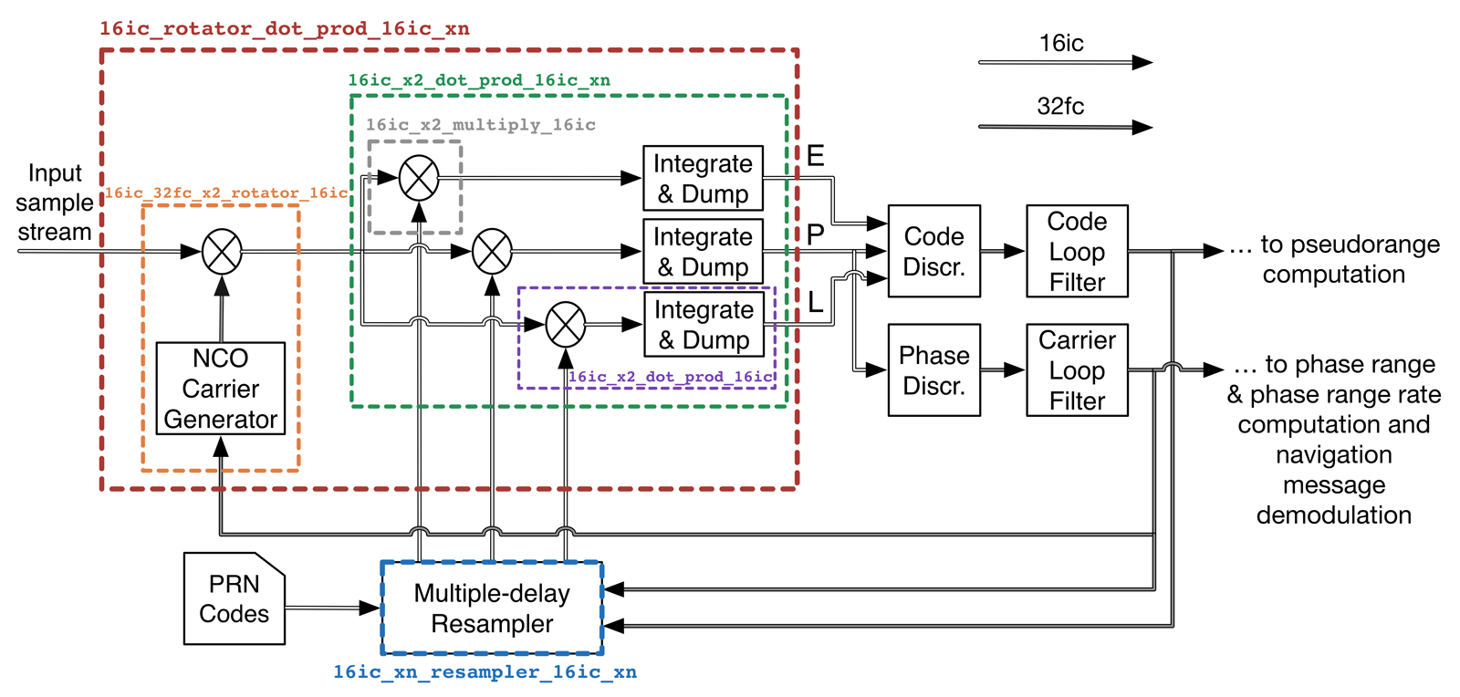 Typical diagram of a tracking block. Colored boxes indicate functions
implemented in the
VOLK_GNSSSDR
library.
Typical diagram of a tracking block. Colored boxes indicate functions
implemented in the
VOLK_GNSSSDR
library.
GNSS-SDR’s Tracking implementations make heavy use of VOLK_GNSSSDR, an extension module of the original VOLK library which contains some functions that are especially useful in the context of a GNSS receiver (some examples in the figure above).
The VOLK_GNSSSDR library addresses Efficiency and Portability at the same time, by providing several implementations of the same functions in different SIMD technologies, benchmarking them and selecting the fastest in your machine at runtime.
Tracking State Machine
The Tracking blocks are continually receiving the data stream \(x_\text{IN}[k]\), but they do nothing until receiving a “positive acquisition” message, along with the coarse estimations \(\hat{\tau}_{acq}\) and \(\hat{f}_{\!D_{acq}}\), provided by an Acquisition block. Then, the role of the Tracking blocks is to refine such estimations and track their changes over time. As shown in the figure below, more refinements can be made once the navigation message bits (in the case of tracking a data component of a GNSS signal) or the secondary spreading code (in the case of tracking a pilot component of a GNSS signal) is synchronized, for instance by extending the integration time or by narrowing the tracking loops.
 Internal state machine of a Tracking block.
Optionally, a passive frequency-error reduction scan, not shown in the figure, can be inserted between the pull-in state and the closed-loop tracking states in order to re-measure the Doppler shift before the loops are closed.
In addition to track the synchronization parameters, the Tracking blocks must also implement code and carrier lock detectors, providing indicators of the tracking performance, as well as an estimation of the carrier-to-noise-density ratio, \(C/N_0\).
Frequency-error reduction scan
The Tracking_<signal>.f_error_step_num option enables a Doppler refinement
scan that the DLL/PLL tracking implementations run every time a channel starts
tracking a satellite, right after the pull-in state and before closing the
tracking loops. It defaults to 0 (scan disabled).
Warning: This option is only available from the next branch of the
upstream GNSS-SDR repository. It will be included in the next stable release.
A navigation-bit or secondary-code sign transition falling inside the coherent integration window of the Acquisition block splits the correlation peak and can displace the Doppler estimate \(\hat{f}_{\!D_{acq}}\) handed over to tracking by more than one acquisition bin. The frequency discriminator described in the Discriminators section below has an unambiguous range of \(\pm \frac{1}{2 T_{int}}\), so for signals with long primary code periods, such as Galileo E1 (\(T_{int} = 4\) ms, that is, \(\pm 125\) Hz), such a displacement can exceed what the FLL is able to pull in, and the loops may take long to converge or fail to lock. The scan re-measures the Doppler shift with the tracking correlators before the loops are closed:
- Once the pull-in state has aligned the local code replica with the code phase
estimated by the Acquisition block, the channel tests
f_error_step_numDoppler hypotheses centered on \(\hat{f}_{\!D_{acq}}\) and spacedf_error_doppler_stepHz apart, visited in the order \(0, +1, -1, +2, -2, \ldots\) times the step. Even values off_error_step_numare rounded up to the next odd number, so that the center bin is always accompanied by the same number of positive and negative offsets. - For each hypothesis, the local carrier is set to that Doppler shift and the
power at the output of the Prompt correlator, \(\vert P[m] \vert^2\), is
non-coherently accumulated over
f_error_accumulationcode periods. The scan is passive: the code phase and the state of the loop filters are left exactly as the pull-in state set them, and no discriminator runs while it lasts. - When all bins have been tested, the Doppler shift of the bin with the highest
accumulated power is retained, the carrier loop filter is re-initialized with
it, and the channel proceeds to the usual closed-loop tracking states. The
selected offset is reported in the log at
INFOlevel.
The scan delays the start of closed-loop tracking, and hence bit or
secondary-code synchronization and the first position fix, by
f_error_step_num \(\times\) f_error_accumulation code periods per channel:
for instance, 9 bins with 5 accumulations each on Galileo E1 (4 ms code period)
take 180 ms. The pull_in_time_s and bit_synchronization_time_limit_s budgets
start counting when the scan completes, so the loops keep their full settling
time. The deliberate frequency steps between bins are not interpreted as signal
dynamics by the Doppler-rate estimator enabled with the high_dyn option.
Since each bin is measured with a coherent integration of one code period, the
accumulated power follows a \(\text{sinc}^2\) envelope with first nulls at
\(\pm 1 / T_{int}\) around the true Doppler shift, and the scan can only
discriminate steps that are a fraction of that width. For signals with short
code periods and sparse bit transitions, such as GPS L1 C/A (1 ms codes, 20 ms
bits), a displaced estimate is infrequent, the FLL pull-in range is wider, and
the resolution of a one-code-period scan is coarse, so the benefit is small.
The option is intended mainly for Galileo E1 and other signals with long code
periods. Choosing f_error_doppler_step well below \(1 / T_{int}\), and a
number of bins such that the total span \(\pm \frac{N-1}{2} \Delta f\) (where
\(N\) is f_error_step_num and \(\Delta f\) is f_error_doppler_step)
covers at least one acquisition Doppler bin on each side, allows the scan to
correct the quantization error of the acquisition grid as well as a
bit-transition displacement. Longer accumulations improve the estimate at low
\(C/N_0\) at the cost of a longer scan.
Each completed scan is also written to the CSV file set by
f_error_dump_filename, which defaults to ./f_error_dump.csv; set this
parameter to an empty value to disable the output. Channels sharing a file name
write to the same file: the first scan of a receiver run overwrites any previous
file and writes a header line, and later scans append their rows. Each row
contains scan_id (a counter identifying the scan), prn, system_char (the
ASCII code of the system identifier, e.g., 71 for G and 69 for E),
channel, cn0_dBHz (an estimate of \(C/N_0\) obtained from the selected
bin), selected_doppler_hz, selected_bin (position of the selected bin in
increasing Doppler order), bin_index, doppler_hz, and power, with one row
per tested bin, sorted by increasing Doppler. The file can be read directly in
Matlab/Octave, e.g., with scans = csvread('f_error_dump.csv', 1, 0);.
For example, this Galileo E1 configuration, in which the acquisition grid has a Doppler step of 125 Hz, tests nine bins spaced 31.25 Hz apart (a span of \(\pm 125\) Hz, that is, one full acquisition bin on each side), accumulating five 4 ms code periods per bin, for a total scan time of 180 ms:
Acquisition_1B.implementation=Galileo_E1_PCPS_Ambiguous_Acquisition
Acquisition_1B.coherent_integration_time_ms=4
Acquisition_1B.doppler_step=125

;... (other parameters) ...

Tracking_1B.implementation=Galileo_E1_DLL_PLL_VEML_Tracking
Tracking_1B.track_pilot=true
Tracking_1B.enable_fll_pull_in=true
Tracking_1B.f_error_step_num=9
Tracking_1B.f_error_doppler_step=31.25
Tracking_1B.f_error_accumulation=5
Tracking_1B.f_error_dump_filename=
This option is supported by the implementations whose parameter tables below
include f_error_step_num.
Carrier-to-noise-density ratio
The carrier-to-noise-density ratio, expressed as \(C/N_0 = \frac{C}{\frac{N}{BW}}\) (where \(C\) is the carrier power, \(N\) is the noise power and \(BW\) is the bandwidth of observation) refers to the ratio of the carrier power and the noise power per unit of bandwidth, so it is expressed in decibel-Hertz (dB-Hz). The term \(\frac{C}{N}\) is known as the signal-to-noise power ratio (SNR).
Considering that the observation bandwidth is the inverse of the coherent integration time, \(T_{int}\), we can write:
\[\begin{equation} C/N_0 = \frac{SNR}{T_{int}}~. \end{equation}\]The SNR estimation for complex signals can be computed as2:
\[\begin{equation} \widehat{SNR} = \frac{\hat{C}}{\hat{N}} = \frac{\sqrt{2 \hat{\mathcal{M}}_2^2 - \hat{\mathcal{M}}_4 }}{\hat{\mathcal{M}}_2 - \sqrt{2 \hat{\mathcal{M}}_2^2 - \hat{\mathcal{M}}_4 }}~, \end{equation}\]where:
- \(\displaystyle \hat{\mathcal{M}}_2 = \frac{1}{M}\sum^{M-1}_{m=0} \vert P[m] \vert^2\) is the estimation of the second moment of \(P[m]\),
- \(\displaystyle \hat{\mathcal{M}}_4 = \frac{1}{M}\sum^{M-1}_{m=0} \vert P[m] \vert^4\) is the estimation of the fourth moment of \(P[m]\),
- \(M\) is the number of samples used to perform the estimation (see tracking block parameter
cn0_samples), - \(\vert \cdot \vert\) is the absolute value (also known as norm, modulus, or magnitude),
- \(P[m]\) is the prompt correlator output (complex value) for the integration period \(m\).
Then, the estimated \(C/N_0\) value in dB-Hz can be written as:
\[\begin{equation} \widehat{C/N}_{0_{dB-Hz}} = 10\log_{10}(\widehat{SNR})-10\log_{10}(T_{int})~. \end{equation}\]This estimation is smoothed with an exponential smoother of the form
\[\begin{equation} {\widehat{C/N}_{0}}_{smoothed}[k] = \alpha \widehat{C/N}_{0}[k] + (1 - \alpha) {\widehat{C/N}_{0}}_{smoothed}[k-1]~, \end{equation}\]with \(\alpha\) controlled by the configuration parameter
cn0_smoother_alpha, after an initialization averaging cn0_smoother_samples
samples.
The \(C/N_0\) value provides an indication of the signal quality that is independent of the acquisition and tracking algorithms used by a receiver, and it remains constant through the different processing stages of the receiver.
The number of correlation outputs to perform the estimation defaults to
\(M = 20\). This value can be changed by using the command line flag -cn0_samples
when running the executable:
$ gnss-sdr -cn0_samples=100 -c=./configuration_file.conf
Code lock detector
The lock detector for the code tracking loop is defined as:
\[\begin{equation} \widehat{C/N}_{0_{dB-Hz}} \overset{\text{lock}}{\underset{\text{no lock}}{\gtrless}} \gamma_{code}~. \end{equation}\]If the estimated \(C/N_{0_{dB-Hz}}\) is above a certain threshold, the tracking loop is declared locked.
The threshold \(\gamma_{code}\) is set by default to 25 dB-Hz. This value can
be changed by using the command line flag -cn0_min when running the
executable:
$ gnss-sdr -cn0_min=22 -c=./configuration_file.conf
Carrier lock detector
The lock detector test for the carrier tracking loop is defined as:
\[\begin{equation} \cos(2\widehat{\Delta \phi}) \overset{\text{lock}}{\underset{\text{no lock}}{\gtrless}} \gamma_{carrier}~, \end{equation}\]where \(\Delta \phi = \phi - \hat{\phi}\) is the carrier phase error. If the estimate of the cosine of twice the carrier phase error is above a certain threshold, the loop is declared in lock.
The estimate of the cosine of twice the carrier phase error is computed as:
\[\begin{equation} \cos\left(2\widehat{\Delta \phi}\right) = \frac{NBD}{NBP}~, \end{equation}\]where:
- \(\displaystyle NBD = \left(\sum^{M-1}_{m=0}P_{Q}[m]\right)^2 - \left(\sum^{M-1}_{i=0}P_{I}[m]\right)^2\),
- \(\displaystyle NBP = \left(\sum^{M-1}_{m=0}P_{Q}[m]\right)^2 + \left(\sum^{M-1}_{i=0}P_{I}[m]\right)^2\),
- \(P_I[m]\) and \(P_Q[m]\) are the prompt correlator output I and Q components for the integration period \(m\).
This estimation is smoothed with an exponential smoother of the form
\[\begin{equation} \!\!\!\!\!\!\!\!\!{\cos(2\widehat{\Delta \phi})}_{smoothed}[k] = \alpha \cos(2\widehat{\Delta \phi})[k] + (1 - \alpha){\cos(2\widehat{\Delta \phi})}_{smoothed}[k-1] \end{equation}\]with \(\alpha\) controlled by the configuration parameter
carrier_lock_test_smoother_alpha, after an initialization averaging
carrier_lock_test_smoother_samples samples.
The threshold \(\gamma_{carrier}\) is set by default to 0.85 radians
(corresponding to an error of approx. 31 degrees). This value can be changed by
using the command line flag -carrier_lock_th when running the executable:
$ gnss-sdr -carrier_lock_th=0.75 -c=./configuration_file.conf
Number of failures allowed before declaring a loss of lock
The maximum number of lock failures before dropping a satellite is set by
default to 50 consecutive failures. This value can be changed by using the
command line flag -max_lock_fail when running the executable:
$ gnss-sdr -max_lock_fail=100 -c=./configuration_file.conf
Discriminators
-
Code Discriminator: For BPSK signals, it is used the DLL noncoherent Early minus Late envelope-normalized discriminator:
\[\begin{equation} \Delta_c[m] = \frac{y_{intercept} - \text{slope} \cdot \epsilon}{\text{slope}} \cdot \frac{\vert E[m]\vert - \vert L[m]\vert}{\vert E[m]\vert + \vert L[m]\vert}~, \end{equation}\]where:
- \(y_{intercept}\) is the interception point of the correlation function in the y-axis,
- \(\text{slope}\) is the slope of the correlation function,
- \(\epsilon\) is the Early-to-Prompt (or Prompt-to-Late) spacing, normalized by the chip period,
- \(\vert E[m]\vert = \sqrt{E_{I}[m]^2 + E_{Q}[m]^2}\) is the magnitude of the Early correlator output,
- \(\vert L[m]\vert = \sqrt{L_{I}[m]^2 + L_{Q}[m]^2}\) is the magnitude of the Late correlator output.
For BOC(1,1) signals, the DLL discriminator is
\[\begin{equation} \Delta_c[m] = \frac{\vert VE[m]\vert + \vert E[m]\vert - \left(\vert VL[m]\vert + \vert L[m]\vert\right)}{\vert VE[m]\vert + \vert E[m]\vert + \vert VL[m]\vert + \vert L[m]\vert}~, \end{equation}\]where:
- \(\vert VE[m]\vert = \sqrt{VE_{I}[m]^2 + VE_{Q}[m]^2}\) is the magnitude of the Very Early correlator output,
- \(\vert VL[m]\vert = \sqrt{VL_{I}[m]^2 + VL_{Q}[m]^2}\) is the magnitude of the Very Late correlator output.
-
Phase Discriminator
PLL Costas loop two-quadrant discriminator for signals with data bit transitions:
\[\begin{equation} \Delta_p^{\text(Costas)}[m] = \text{arctan} \left(\frac{P_{Q}[m]}{P_{I}[m]}\right)~. \end{equation}\]PLL four-quadrant discriminator for dataless channels:
\[\begin{equation} \Delta_p^{\text(atan2)}[m] = \text{arctan2} \left(P_{Q}[m], P_{I}[m]\right)~. \end{equation}\] -
Frequency Discriminator
If the Frequency Locked Loop (FLL) is activated, the receiver uses the four-quadrant discriminator:
\[\begin{equation} \Delta_f[m] = \frac{1}{T_{int}}\text{arctan2}\left(\text{cross}[m], \text{dot}[m]\right)~, \end{equation}\]where
\[\text{cross}[m] = P_{I}[k-1]P_{Q}[m] - P_{I}[m]P_{Q}[k-1]\]and
\[\text{dot}[m] = P_{I}[k-1]P_{I}[m] + P_{Q}[k-1]P_{Q}[m]~.\]
Low pass filters
Diagrams of digital low-pass filters of different order are shown below:
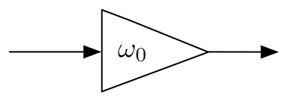 First-order digital low-pass filter.
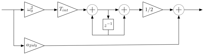 Second-order digital low-pass filter.
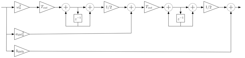 Third-order digital low-pass filter.
| Filter order | Parameters |
|---|---|
| First | \(\omega_0 = 0.25 \cdot \text{BW}\) |
| Second | \(\omega_0= \frac{\text{BW}}{0.53}\), \(a_2=1.414\) |
| Third | \(\omega_0= \frac{\text{BW}}{0.7845}\), \(a_3=1.1\), \(b_3=2.4\) |
Filter parameters, from Kaplan & Hegarty3.
The user can configure the noise bandwidth with parameters dll_bw_hz and
pll_bw_hz, and the filter order with dll_filter_order and
pll_filter_order.
The configuration interfaces for the available Tracking block implementations are described below.
GPS L1 C/A signal tracking
This signal, centered at \(f_{\text{GPS L1}} = 1575.42\) MHz, has a complex baseband transmitted signal that can be written as:
\[\begin{equation} \label{GPSL1} s^{\text{(GPS L1)}}_{T}(t)=e_{L1I}(t) + j e_{L1Q}(t)~, \end{equation}\]with
\[\begin{equation} e_{L1I}(t) = \sum_{l=-\infty}^{\infty} D_{\text{NAV}}\Big[ [l]_{204600}\Big] \oplus C_{\text{P(Y)}} \Big[ |l|_{L_{\text{P(Y)}}} \Big] p(t - lT_{c,\text{P(Y)}})~, \end{equation}\] \[\begin{equation} e_{L1Q}(t) = \sum_{l=-\infty}^{\infty} D_{\text{NAV}}\Big[ [l]_{20460} \Big] \oplus C_{\text{C/A}} \Big[ |l|_{1023} \Big] p(t - lT_{c,\text{C/A}})~, \end{equation}\]where \(\oplus\) is the exclusive–or operation (modulo–2 addition), \(|l|_{L}\) means \(l\) modulo \(L\), \([l]_{L}\) means the integer part of \(\frac{l}{L}\), \(D_{\text{NAV}}\) is the GPS navigation message bit sequence, transmitted at \(50\) bit/s, \(T_{c,\text{P(Y)}} = \frac{1}{10.23}\) \(\mu\)s, \(T_{c,\text{C/A}} = \frac{1}{1.023}\) \(\mu\)s, \(L_{\text{P(Y)}} =6.1871 \cdot 10^{12}\), and \(p(t)\) is the chip pulse of a chip–period duration.
Then, applying equation \((\ref{GPSL1})\) in \((\ref{xin})\), the digital signal at the input of the Tracking block can be written as:
\[\begin{equation} \!\!\!\!\!\!\!\!\! x_\text{IN}[k] = A(kT_s)\tilde{s}^{\text{(GPS L1)}}_{T}(kT_s - \tau(kT_s)) e^{j \left(2\pi f_D(kT_s) kT_s + \phi(kT_s) \right) } + n(kT_s)~. \end{equation}\]The implementations described below perform the estimation of \(\tau\), \(f_D\) and \(\phi\), which are assumed piecewise constant (that is, constant within an integration time, but allowed to vary from one integration period to the next one).
Implementation: GPS_L1_CA_DLL_PLL_Tracking
This implementation accepts the following parameters:
| Global Parameter | Description | Required |
|---|---|---|
GNSS-SDR.internal_fs_sps |
Input sample rate to the processing channels, in samples per second. | Mandatory |
| Parameter | Description | Required |
|---|---|---|
implementation |
GPS_L1_CA_DLL_PLL_Tracking |
Mandatory |
item_type |
[gr_complex]: Set the sample data type expected at the block input. It defaults to gr_complex. |
Optional |
extend_correlation_symbols |
Sets the number of correlation symbols to be extended after bit synchronization has been achieved. Each symbol is 1 ms, so setting this parameter to 20 means a coherent integration time of 20 ms. Each bit is 20 ms, so the value of this parameter must be a divisor of it (e.g., 2, 4, 5, 10, 20). The higher this parameter is, the better local clock stability will be required. It defaults to 1. | Optional |
pll_bw_hz |
Bandwidth of the PLL low-pass filter, in Hz. It defaults to 50 Hz. | Optional |
pll_bw_narrow_hz |
Bandwidth of the PLL low-pass filter after bit synchronization, in Hz. It defaults to 20 Hz. | Optional |
pll_filter_order |
[2, 3]. Sets the order of the PLL low-pass filter. It defaults to 3. |
Optional |
enable_fll_pull_in |
[true, false]. If set to true, enables the FLL during the pull-in time. It defaults to false. |
Optional |
enable_fll_steady_state |
[true, false]. If set to true, the FLL is enabled beyond the pull-in stage. It defaults to false. |
Optional |
fll_bw_hz |
Bandwidth of the FLL low-pass filter, in Hz. It defaults to 35 Hz. | Optional |
pull_in_time_s |
Time, in seconds, in which the tracking loop will be in pull-in mode. It defaults to 5 s. | Optional |
f_error_step_num |
Number of Doppler bins tested by the frequency-error reduction scan run after the pull-in stage, centered on the Doppler estimate provided by the Acquisition block. Even values are rounded up to the next odd number. It defaults to 0 (scan disabled). See Frequency-error reduction scan for availability, tradeoffs, and interactions. | Optional |
f_error_doppler_step |
Spacing between consecutive Doppler bins of the frequency-error reduction scan, in Hz. Only used if f_error_step_num \(>\) 0. It defaults to 250 Hz. |
Optional |
f_error_accumulation |
Number of code periods over which the Prompt correlator power is non-coherently accumulated in each Doppler bin of the frequency-error reduction scan. Only used if f_error_step_num \(>\) 0; a value of 0 is replaced by 1. It defaults to 20. |
Optional |
f_error_dump_filename |
Name of the CSV file in which the results of each frequency-error reduction scan are written. Only used if f_error_step_num \(>\) 0. Set it to an empty value to disable this output. It defaults to ./f_error_dump.csv. |
Optional |
dll_bw_hz |
Bandwidth of the DLL low-pass filter, in Hz. It defaults to 2 Hz. | Optional |
dll_bw_narrow_hz |
Bandwidth of the DLL low-pass filter after bit synchronization, in Hz. It defaults to 2 Hz. | Optional |
dll_filter_order |
[1, 2, 3]. Sets the order of the DLL low-pass filter. It defaults to 2. |
Optional |
early_late_space_chips |
Spacing between Early and Prompt and between Prompt and Late correlators, normalized by the chip period \(T_c\). It defaults to \(0.5\). | Optional |
early_late_space_narrow_chips |
Spacing between Early and Prompt and between Prompt and Late correlators, normalized by the chip period \(T_c\), after bit synchronization. It defaults to \(0.5\). | Optional |
carrier_aiding |
[true, false]. If set to true, the code loop is aided by the carrier loop. It defaults to true. |
Optional |
cn0_samples |
Number of \(P\) correlator outputs used for CN0 estimation. It defaults to 20. | Optional |
cn0_min |
Minimum valid CN0 (in dB-Hz). It defaults to 25 dB-Hz. | Optional |
max_lock_fail |
Maximum number of lock failures before dropping a satellite. It defaults to 50. | Optional |
carrier_lock_th |
Carrier lock threshold (in rad). It defaults to 0.85 rad. | Optional |
cn0_smoother_samples |
Number of samples used to smooth the value of the estimated \(C/N_0\). It defaults to 200 samples. | Optional |
cn0_smoother_alpha |
Forgetting factor of the \(C/N_0\) smoother, as in \(y_k = \alpha x_k + (1 - \alpha) y_{k-1}\). It defaults to 0.002. | Optional |
carrier_lock_test_smoother_samples |
Number of samples used to smooth the value of the carrier lock test. It defaults to 25 samples. | Optional |
carrier_lock_test_smoother_alpha |
Forgetting factor of the carrier lock detector smoother, as in \(y_k = \alpha x_k + (1 - \alpha) y_{k-1}\). It defaults to 0.002. | Optional |
dump |
[true, false]: If set to true, it enables the Tracking internal binary data file logging, in form of “.dat” files. This format can be retrieved and plotted in Matlab / Octave, see scripts under gnss-sdr/utils/matlab/. It defaults to false. |
Optional |
dump_filename |
If dump is set to true, name of the file in which internal data will be stored. This parameter accepts either a relative or an absolute path; if there are non-existing specified folders, they will be created. It defaults to ./track_ch, so files in the form “./track_chX.dat”, where X is the channel number, will be generated. |
Optional |
dump_mat |
[true, false]. If dump=true, when the receiver exits it can convert the “.dat” files stored by this block into “.mat” files directly readable from Matlab and Octave. If the receiver has processed more than a few minutes of signal, this conversion can take a long time. In systems with limited resources, you can turn off this conversion by setting this parameter to false. It defaults to true, so “.mat” files are generated by default if dump=true. |
Optional |
Tracking implementation: GPS_L1_CA_DLL_PLL_Tracking.
Example:
;######### TRACKING CONFIG FOR GPS L1 CHANNELS ############
Tracking_1C.implementation=GPS_L1_CA_DLL_PLL_Tracking
Tracking_1C.item_type=gr_complex
Tracking_1C.extend_correlation_symbols=20
Tracking_1C.early_late_space_chips=0.5;
Tracking_1C.early_late_space_narrow_chips=0.1;
Tracking_1C.pll_bw_hz=35;
Tracking_1C.dll_bw_hz=2.0;
Tracking_1C.pll_bw_narrow_hz=5.0;
Tracking_1C.dll_bw_narrow_hz=0.50;
Tracking_1C.fll_bw_hz=10
Tracking_1C.enable_fll_pull_in=true;
Tracking_1C.enable_fll_steady_state=false
Tracking_1C.dump=false
Tracking_1C.dump_filename=tracking_ch_
Implementation: GPS_L1_CA_DLL_PLL_Tracking_GPU
GPU-accelerated computing consists of the use of a graphics processing unit (GPU) together with a CPU to accelerate the execution of a software application, by offloading computation-intensive portions of the application to the GPU, while the remainder of the code still runs on the CPU. The key idea is to utilize the computation power of both CPU cores and GPU execution units in tandem for better utilization of available computing power.
This implementation follows the CUDA programming model and targets NVIDIA’s GPU
computing platform. Thus, you will need a CUDA-enabled
GPU and the CUDA
Toolkit installed. Moreover, it is
only available if GNSS-SDR has been built from source and configured with the
flag ENABLE_CUDA set to ON:
$ cmake -DENABLE_CUDA=ON ../ && make && sudo make install
This implementation accepts the following parameters:
| Global Parameter | Description | Required |
|---|---|---|
GNSS-SDR.internal_fs_sps |
Input sample rate to the processing channels, in samples per second. | Mandatory |
| Parameter | Description | Required |
|---|---|---|
implementation |
GPS_L1_CA_DLL_PLL_Tracking_GPU |
Mandatory |
item_type |
[gr_complex]: Set the sample data type expected at the block input. It defaults to gr_complex. |
Optional |
pll_bw_hz |
Bandwidth of the PLL low-pass filter, in Hz. It defaults to 50 Hz. | Optional |
dll_bw_hz |
Bandwidth of the DLL low-pass filter, in Hz. It defaults to 2 Hz. | Optional |
early_late_space_chips |
Spacing between Early and Prompt and between Prompt and Late correlators, normalized by the chip period \(T_c\). It defaults to \(0.5\). | Optional |
dump |
[true, false]: If set to true, it enables the Tracking internal binary data file logging. It defaults to false. |
Optional |
dump_filename |
If dump is set to true, name of the file in which internal data will be stored. It defaults to ./track_ch |
Optional |
Tracking implementation: GPS_L1_CA_DLL_PLL_Tracking_GPU.
Example:
;######### TRACKING CONFIG FOR GPS L1 CHANNELS ############
Tracking_1C.implementation=GPS_L1_CA_DLL_PLL_Tracking_GPU
Tracking_1C.pll_bw_hz=40.0;
Tracking_1C.dll_bw_hz=4.0;
Galileo E1 signal tracking
This band, centered at \(f_{\text{Gal E1}} = 1575.420\) MHz and with a reference bandwidth of \(24.5520\) MHz, uses the Composite Binary Offset Carrier (CBOC) modulation, defined in baseband as:
\[\begin{eqnarray} s^{\text{(Gal E1)}}_{T}(t) & = & \frac{1}{\sqrt{2}} \Big( e_{E1B}(t)\left(\alpha sc_A(t) + \beta sc_B(t) \right) + \nonumber \\ {} & {} & - ~e_{E1C}(t) \left(\alpha sc_A(t) - \beta sc_B(t) \right) \Big)~, \label{GalE1} \end{eqnarray}\]where the subcarriers \(sc(t)\) are defined as
\[\begin{equation} sc_A(t) = \text{sign} \Big(\sin(2\pi f_{s,E1A}t) \Big)~, \end{equation}\] \[\begin{equation} sc_B(t) = \text{sign} \Big(\sin(2\pi f_{s,E1B}t) \Big)~, \end{equation}\]and \(f_{s,E1A} = 1.023\) MHz, \(f_{s, E1B} =6.138\) MHz are the subcarrier rates, \(\alpha= \sqrt{\frac{10}{11}}\), and \(\beta= \sqrt{\frac{1}{11}}\). Channel B contains the I/NAV type of navigation message, \(D_{I/NAV}\), intended for Safety–of–Life (SoL) services:
\[\begin{equation} e_{E1B}(t) = \sum_{l=-\infty}^{+\infty} D_{\text{I/NAV}} \Big[[l]_{4092}\Big] \oplus C_{E1B}\Big[|l|_{4092}\Big] p(t - lT_{c,E1B})~. \end{equation}\]In case of channel C, it is a pilot (dataless) channel with a secondary code, forming a tiered code:
\[\begin{equation} \!\!\!\!\!\!\!\!\!\!\!\!\!\!e_{E1C}(t) \! = \!\! \sum_{m=-\infty}^{+\infty} \! C_{E1Cs}\Big[|m|_{25}\Big] \oplus \sum_{l=1}^{4092}C_{E1Cp}\Big[ l \Big] \cdot p(t \! - \! mT_{c,E1Cs} \! - \! lT_{c,E1Cp})~, \end{equation}\]with \(T_{c,E1B} = T_{c,E1Cp} = \frac{1}{1.023}\) \(\mu\)s and \(T_{c,E1Cs} = 4\) ms.
Then, applying equation \((\ref{GalE1})\) in \((\ref{xin})\), the digital signal at the input of the Tracking block can be written as
\[\begin{equation} \!\!\!\!\!\!\!\!\!x_\text{IN}[k] = A(kT_s)\tilde{s}^{\text{(Gal E1)}}_{T}(kT_s - \tau(kT_s)) e^{j \left( 2\pi f_D(kT_s) kT_s + \phi(kT_s) \right) } + n(kT_s)~. \end{equation}\]The implementation described below performs the estimation of \(\tau\), \(f_D\) and \(\phi\), which are assumed piecewise constant (that is, constant within an integration time, but allowed to vary from one integration period to the next one).
Implementation: Galileo_E1_DLL_PLL_VEML_Tracking
In case of Galileo E1, the CBOC(6,1,\(\frac{1}{11}\)) modulation creates correlation ambiguities, as shown in the following figure:
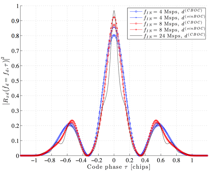 Normalized \(\left|R_{xd}\left(\check{f}_D = f_D, \tau \right) \right|^2\) for different sampling rates and local reference waveforms4.
The possibility of tracking a local maximum instead of the global one can be avoided by using discriminators that consider two extra samples of the cost function, referred to as Very Early \(\text{VE} = R_{xd}(\hat{\tau}-\epsilon^\prime)\) and Very Late \(\text{VL} = R_{xd}(\hat{\tau}+\epsilon^\prime)\), with \(\epsilon^\prime > \epsilon\).
In the case of carrier tracking loops, the pilot channel E1C can be used for the phase error estimation, since it does not contain data bit transitions, and, theoretically, coherent integration of several code periods can be used for as long as needed once the secondary code has been removed. As a consequence, a discriminator that is insensitive to phase jumps can be used. Using pure PLL tracking on the pilot channel as well as longer coherent integration improves the carrier tracking sensitivity, the minimum signal power at which the receiver can keep the tracking process in lock.
The implementation of this block is described in the Algorithm below. The computation of the complex values VE, E, P, L and VL in step \(5\) was implemented using the VOLK_GNSSSDR library. The PLL discriminator implemented in step \(6\) is the extended arctangent (four-quadrant) discriminator, and for the DLL we used the normalized Very Early Minus Late Power discriminator (step \(10\)). The low-pass filters of the DLL, PLL, and FLL (when available, see implementations below) are based in the description by Kaplan and Hegarty3, section 8.8. For code lock detection (step \(13\)), we used the Squared Signal-to-Noise Variance (SNV) estimator5. In the case of carrier lock detection (step \(14\)), we used the normalized estimate of the cosine of twice the carrier phase6. The values of the lock indicator range from \(-1\), when the locally generated carrier is completely out of phase, to \(1\), that indicates a perfect match. When either the code or the carrier detectors are below given thresholds during a consecutive number of code periods \(\vartheta\), the Tracking block informs to control plane through the message queue.
- Require: Complex sample stream, \(\mathbf{x}_{\text{IN}}\); estimations of code phase \(\hat{\tau}_{acq}\) and Doppler shift \(\hat{f}_{\!D_{acq}}\); buffer size for power estimation, \(\mathcal{U}\); carrier lock detector threshold, \(\mathcal{T}\); \(CN0_{min}\); maximum value for the lock fail counter, \(\vartheta\); correlators spacing \(\epsilon\) and \(\epsilon^\prime\); loop filters bandwidth \(BW_{DLL}\) and \(BW_{PLL}\); integration time \(T_{int}\). Track signal’s synchronization parameters within a given lock margin. Inform about a loss of lock.
-
Initialization: Using \(\hat{\tau}_{acq}\) and a sample counter \(\mathcal{N}\), skip samples until \(\mathbf{x}_{\text{IN}}\) is aligned with local PRN replica. Set \(\upsilon = 0\), \(k = 0\), \(\hat{f}_{\!D_{0}} = \hat{f}_{\!D_{acq}}\), \(\hat{\phi}_0 = 0\), \(\psi_1 = 0\), \(N_1 = \text{round}(T_{int} f_{\text{IN}})\).
-
Increase the integration period counter: \(k=k+1\).
- Generate local code references: for \(n=1...N_k\), \(s[n] = d_{E1B/E1C_{p}}\left[\text{round}(\delta_{k} \cdot n + \psi_{k})\right]\), where \(\delta_{k} = \frac{1}{T_{c,E1B} \cdot f_{\text{IN}} }\left(1 + \frac{\hat{f}_{\!D_{k-1}}}{f^{\text{(Gal E1)}}_c} \right)\), and the Very Early, Early, Late, and Very Late versions with \(\epsilon\) and \(\epsilon^\prime\).
-
Generate local carrier: for \(n=1...N_k\), \(c[n] = e^{-j\left(2\pi \hat{f}_{\!D_{k-1}} \frac{n}{f_{\text{IN}}}+\text{mod}\left(\hat{\phi}_{k-1},2\pi \right) \right)}\).
-
Perform carrier wipe-off and compute the complex samples VE\(_k\), E\(_k\), P\(_k\), L\(_k\) and VL\(_k\). Example: \(\text{P}_k = \frac{1}{N_k} \sum_{n=0}^{N_k-1} x_{\text{IN}}[n] s[n] c[n]\).
-
Compute PLL discriminator: \(\Delta \hat{\phi}_{k} = \mbox{atan2}\left( \frac{ \text{P}_{Q_{k}}}{\text{P}_{I_{k}}} \right)\)
-
Filter \(\Delta \hat{\phi}_{k}\) with a bandwidth \(BW_{PLL}\): \(h_{PLL}\left(\Delta \hat{\phi}_{k}\right)\).
-
Update carrier frequency estimation (in Hz): \(\hat{f}_{\!D_{k}} = \hat{f}_{\!D_{acq}} + \frac{1}{2\pi T_{int}} h_{PLL}\left( \Delta \hat{\phi}_{k} \right)\).
-
Update carrier phase estimation (in rad): \(\hat{\phi}_k = \hat{\phi}_{k-1} + 2 \pi \hat{f}_{\!D_{k}} T_{int} + h_{PLL}(\Delta \hat{\phi})\).
-
Compute DLL discriminator: \(\Delta \hat{\tau}_{k} = \frac{\mathcal{E}_{k} - \mathcal{L}_{k}}{\mathcal{E}_{k} + \mathcal{L}_{k}}\), where: \(\mathcal{E}_{k} = \sqrt{\text{VE}_{I_{k}}^2 + \text{VE}_{Q_{k}}^2 + E_{I_{k}}^2 + E_{Q_{k}}^2}\), and \(\mathcal{L}_{k} = \sqrt{\text{VL}_{I_{k}}^2 + \text{VL}_{Q_{k}}^2 + L_{I_{k}}^2 + L_{Q_{k}}^2}\).
-
Filter \(\Delta \hat{\tau}_{k}\) with a bandwidth \(BW_{DLL}\): \(h_{DLL}\left( \Delta \hat{\tau}_{k}\right)\).
-
Update code phase estimation (in samples): \(N_{k+1} = \text{round}(S)\) and \(\psi_{k+1} = S - N_{k+1}\), where \(S = \frac{T_{int}f_{\text{IN}}}{\left(1 + \frac{\hat{f}_{D_{k}}}{f^{\text{(Gal E1)}}_c} \right)} + \psi_{k} + h_{DLL}(\hat{\Delta \tau}_k)f_{\text{IN}}\).
-
Code lock indicator: \(\hat{ \text{CN0} } = 10 \cdot \log_{10}\left(\hat{\rho}\right) + 10 \cdot \log_{10}\left(\frac{f_{\text{IN}}}{2}\right) - 10 \cdot \log_{10} \left(L_{\text{PRN}}\right)\), where: \(\hat{\rho} = \frac{ \hat{P}_s }{ \hat{P}_n } = \frac{\hat{P}_s}{\hat{P}_{tot} - \hat{P}_s}\), \(\hat{P}_s = \left(\frac{1}{\mathcal{U}}\sum^{\mathcal{U}-1}_{i=0}|\text{P}_{I_{k-i}} |\right)^2\), and \(\hat{P}_{tot} = \frac{1}{\mathcal{U}}\sum^{\mathcal{U}-1}_{i=0}|\text{P}_{k-i}|^2\).
-
Phase lock indicator: \(T_{carrier} = \frac{\left( \sum^{\mathcal{U}-1}_{i=0} \text{P}_{I_{k-i}}\right)^2 - \left( \sum^{\mathcal{U} - 1}_{i=0} \text{P}_{Q_{k-i}}\right)^2}{\left(\sum^{\mathcal{U}-1}_{i=0} \text{P}_{ {I}_{k-i}}\right)^2 + \left( \sum^{\mathcal{U} - 1}_{i=0} \text{P}_{Q_{k-i}}\right)^2}\).
- if \(T_{carrier} < \mathcal{T}\) or \(\hat{ CN0 } < CN0_{min}\)
- Increase lock fail counter \(\upsilon \leftarrow \upsilon + 1\).
- else
- Decrease lock fail counter \(\upsilon \leftarrow \max(\upsilon - 1,0)\).
-
endif
- if \(\upsilon > \vartheta\)
- Notify the loss of lock to the control plane through the message queue.
-
endif
- Output: \(\text{P}_k\), accumulated carrier phase error \(\hat{\phi}_k\), code phase \(\mathcal{N} \leftarrow \mathcal{N} + N_k + \psi_k\), carrier-to-noise-density ratio \(\hat{\text{CN0}}\).
This implementation accepts the following parameters:
| Global Parameter | Description | Required |
|---|---|---|
GNSS-SDR.internal_fs_sps |
Input sample rate to the processing channels, in samples per second. | Mandatory |
| Parameter | Description | Required |
|---|---|---|
implementation |
Galileo_E1_DLL_PLL_VEML_Tracking |
Mandatory |
item_type |
[gr_complex]: Set the sample data type expected at the block input. It defaults to gr_complex. |
Optional |
track_pilot |
[true, false]: If set to true, the receiver is set to track the pilot signal E1C and enables an extra prompt correlator (slave to pilot’s prompt) in the data component E1B. If set to false, the receiver performs correlations on a data length of 4 ms over the E1B component. This parameter defaults to true. |
Optional |
extend_correlation_symbols |
If track_pilot=true, sets the number of correlation symbols to be extended after the secondary code \(C_{E1C_{s}}\) is removed from the pilot signal, in number of symbols. Each symbol is 4 ms, so setting this parameter to 25 means a coherent integration time of 100 ms. The higher this parameter is, the better local clock stability will be required. It defaults to 1. |
Optional |
pll_bw_hz |
Bandwidth of the PLL low-pass filter, in Hz. It defaults to 50 Hz. | Optional |
pll_bw_narrow_hz |
If track_pilot=true and extend_correlation_symbols \(>\) 1, sets the bandwidth of the PLL low-pass filter after removal of the secondary code \(C_{E1C_{s}}\), in Hz. It defaults to 2 Hz. This implementation uses a four-quadrant arctangent discriminator (atan2). |
Optional |
pll_filter_order |
[2, 3]. Sets the order of the PLL low-pass filter. It defaults to 3. |
Optional |
enable_fll_pull_in |
[true, false]. If set to true, enables the FLL during the pull-in time. It defaults to false. |
Optional |
enable_fll_steady_state |
[true, false]. If set to true, the FLL is enabled beyond the pull-in stage. It defaults to false. |
Optional |
fll_bw_hz |
Bandwidth of the FLL low-pass filter, in Hz. It defaults to 35 Hz. | Optional |
pull_in_time_s |
Time, in seconds, in which the tracking loop will be in pull-in mode. It defaults to 5 s. | Optional |
f_error_step_num |
Number of Doppler bins tested by the frequency-error reduction scan run after the pull-in stage, centered on the Doppler estimate provided by the Acquisition block. Even values are rounded up to the next odd number. It defaults to 0 (scan disabled). See Frequency-error reduction scan for availability, tradeoffs, and interactions. | Optional |
f_error_doppler_step |
Spacing between consecutive Doppler bins of the frequency-error reduction scan, in Hz. Only used if f_error_step_num \(>\) 0. It defaults to 250 Hz. |
Optional |
f_error_accumulation |
Number of code periods over which the Prompt correlator power is non-coherently accumulated in each Doppler bin of the frequency-error reduction scan. Only used if f_error_step_num \(>\) 0; a value of 0 is replaced by 1. It defaults to 20. |
Optional |
f_error_dump_filename |
Name of the CSV file in which the results of each frequency-error reduction scan are written. Only used if f_error_step_num \(>\) 0. Set it to an empty value to disable this output. It defaults to ./f_error_dump.csv. |
Optional |
dll_bw_hz |
Bandwidth of the DLL low-pass filter, in Hz. It defaults to 2 Hz. | Optional |
dll_bw_narrow_hz |
If track_pilot=true and extend_correlation_symbols \(>\) 1, sets the bandwidth of the DLL low-pass filter after removal of the secondary code \(C_{E1C_{s}}\) and extension of the coherent integration time, in Hz. It defaults to 0.25 Hz. |
Optional |
dll_filter_order |
[1, 2, 3]. Sets the order of the DLL low-pass filter. It defaults to 2. |
Optional |
early_late_space_chips |
Spacing between Early and Prompt and between Prompt and Late correlators, normalized by the chip period \(T_c\). It defaults to \(0.15\). | Optional |
very_early_late_space_chips |
Spacing between Very Early and Prompt and between Prompt and Very Late correlators, normalized by the chip period \(T_c\) It defaults to \(0.6\). | Optional |
early_late_space_narrow_chips |
If track_pilot=true and extend_correlation_symbols \(>\) 1, sets the spacing between Early and Prompt and between Prompt and Late correlators after removal of the secondary code \(C_{E1C_{s}}\), normalized by the chip period \(T_c\). It defaults to \(0.15\). |
Optional |
very_early_late_space_narrow_chips |
If track_pilot=true and extend_correlation_symbols \(>\) 1, sets the spacing between Very Early and Prompt and between Prompt and Very Late correlators after removal of the secondary code \(C_{E1C_{s}}\) and extension of the coherent integration time, normalized by the chip period \(T_c\). It defaults to \(0.6\). |
Optional |
carrier_aiding |
[true, false]. If set to true, the code loop is aided by the carrier loop. It defaults to true. |
Optional |
cn0_samples |
Number of \(P\) correlator outputs used for CN0 estimation. It defaults to 20. | Optional |
cn0_min |
Minimum valid CN0 (in dB-Hz). It defaults to 25 dB-Hz. | Optional |
max_lock_fail |
Maximum number of lock failures before dropping a satellite. It defaults to 50. | Optional |
carrier_lock_th |
Carrier lock threshold (in rad). It defaults to 0.85 rad. | Optional |
cn0_smoother_samples |
Number of samples used to smooth the value of the estimated \(C/N_0\). It defaults to 200 samples. | Optional |
cn0_smoother_alpha |
Forgetting factor of the \(C/N_0\) smoother, as in \(y_k = \alpha x_k + (1 - \alpha) y_{k-1}\). It defaults to 0.002. | Optional |
carrier_lock_test_smoother_samples |
Number of samples used to smooth the value of the carrier lock test. It defaults to 25 samples. | Optional |
carrier_lock_test_smoother_alpha |
Forgetting factor of the carrier lock detector smoother, as in \(y_k = \alpha x_k + (1 - \alpha) y_{k-1}\). It defaults to 0.002. | Optional |
dump |
[true, false]: If set to true, it enables the Tracking internal binary data file logging, in form of “.dat” files. This format can be retrieved and plotted in Matlab / Octave, see scripts under gnss-sdr/utils/matlab/. It defaults to false. |
Optional |
dump_filename |
If dump is set to true, name of the file in which internal data will be stored. This parameter accepts either a relative or an absolute path; if there are non-existing specified folders, they will be created. It defaults to ./track_ch, so files in the form “./track_chX.dat”, where X is the channel number, will be generated. |
Optional |
dump_mat |
[true, false]. If dump=true, when the receiver exits it can convert the “.dat” files stored by this block into “.mat” files directly readable from Matlab and Octave. If the receiver has processed more than a few minutes of signal, this conversion can take a long time. In systems with limited resources, you can turn off this conversion by setting this parameter to false. It defaults to true, so “.mat” files are generated by default if dump=true. |
Optional |
Tracking implementation: Galileo_E1_DLL_PLL_VEML_Tracking.
Example:
;######### TRACKING CONFIG FOR GALILEO E1 CHANNELS ############
Tracking_1B.implementation=Galileo_E1_DLL_PLL_VEML_Tracking
Tracking_1B.item_type=gr_complex
Tracking_1B.track_pilot=true
Tracking_1B.pll_bw_hz=15.0;
Tracking_1B.dll_bw_hz=0.75;
Tracking_1B.early_late_space_chips=0.25;
Tracking_1B.early_late_space_narrow_chips=0.15;
Tracking_1B.very_early_late_space_chips=0.5;
Tracking_1B.very_early_late_space_narrow_chips=0.5;
Tracking_1B.pll_bw_narrow_hz=5.0
Tracking_1B.dll_bw_narrow_hz=0.2
Tracking_1B.extend_correlation_symbols=5
Tracking_1B.enable_fll_pull_in=true;
Tracking_1B.enable_fll_steady_state=false
Tracking_1B.fll_bw_hz=10
Tracking_1B.dump=false
Tracking_1B.dump_filename=tracking_ch_
Glonass L1 C/A signal tracking
The complex baseband transmitted signal can be written as:
\[\begin{equation} \label{GLOL1} s^{\text{(GLO L1)}}_{T}(t) = e_{L1I}(t) + j e_{L1Q}(t)~, \end{equation}\]with
\[\begin{equation} e_{L1I}(t) = \sum_{l=-\infty}^{\infty} D_{\text{GNAV}}\Big[ [l]_{102200}\Big] \oplus C_{\text{HP}} \Big[ |l|_{L_{\text{HP}}} \Big] p(t - lT_{c,\text{HP}})~, \end{equation}\] \[\begin{equation} e_{L1Q}(t) = \sum_{l=-\infty}^{\infty} D_{\text{GNAV}}\Big[ [l]_{10220} \Big] \oplus C_{\text{C/A}} \Big[ |l|_{511} \Big] p(t - lT_{c,\text{C/A}})~, \end{equation}\]where \(T_{c,\text{HP}} = \frac{1}{5.11}\) \(\mu\)s, \(T_{c,\text{C/A}} = \frac{1}{0.511}\) \(\mu\)s, and \(L_{\text{HP}} = 3.3554\cdot 10^7\). The navigation message \(D_{\text{GNAV}}\) is transmitted at \(50\) bit/s.
Then, applying equation \((\ref{GLOL1})\) in \((\ref{xin})\), the digital signal at the input of the Tracking block can be written as
\[\begin{equation} \!\!\!\!\!\!\!\!\!x_\text{IN}[k] = A(kT_s)\tilde{s}^{\text{(GLO L1)}}_{T}(kT_s - \tau(kT_s)) e^{j \left(2\pi f_D(kT_s) kT_s + \phi(kT_s) \right)} + n(kT_s)~. \end{equation}\]The implementations described below perform the estimation of \(\tau\), \(f_D\) and \(\phi\), which are assumed piecewise constant (that is, constant within an integration time, but allowed to vary from one integration period to the next one).
Implementation: GLONASS_L1_CA_DLL_PLL_Tracking
This implementation accepts the following parameters:
| Global Parameter | Description | Required |
|---|---|---|
GNSS-SDR.internal_fs_sps |
Input sample rate to the processing channels, in samples per second. | Mandatory |
| Parameter | Description | Required |
|---|---|---|
implementation |
GLONASS_L1_CA_DLL_PLL_Tracking |
Mandatory |
item_type |
[gr_complex]: Set the sample data type expected at the block input. It defaults to gr_complex. |
Optional |
pll_bw_hz |
Bandwidth of the PLL low-pass filter, in Hz. It defaults to 50 Hz. | Optional |
dll_bw_hz |
Bandwidth of the DLL low-pass filter, in Hz. It defaults to 2 Hz. | Optional |
early_late_space_chips |
Spacing between Early and Prompt and between Prompt and Late correlators, normalized by the chip period \(T_c\). It defaults to \(0.5\). | Optional |
f_error_step_num |
Number of Doppler bins tested by the frequency-error reduction scan run after the pull-in stage, centered on the Doppler estimate provided by the Acquisition block. Even values are rounded up to the next odd number. It defaults to 0 (scan disabled). See Frequency-error reduction scan for availability, tradeoffs, and interactions. | Optional |
f_error_doppler_step |
Spacing between consecutive Doppler bins of the frequency-error reduction scan, in Hz. Only used if f_error_step_num \(>\) 0. It defaults to 250 Hz. |
Optional |
f_error_accumulation |
Number of code periods over which the Prompt correlator power is non-coherently accumulated in each Doppler bin of the frequency-error reduction scan. Only used if f_error_step_num \(>\) 0; a value of 0 is replaced by 1. It defaults to 20. |
Optional |
f_error_dump_filename |
Name of the CSV file in which the results of each frequency-error reduction scan are written. Only used if f_error_step_num \(>\) 0. Set it to an empty value to disable this output. It defaults to ./f_error_dump.csv. |
Optional |
dump |
[true, false]: If set to true, it enables the Tracking internal binary data file logging. Binary data can be retrieved and plotted in Matlab / Octave, see scripts under gnss-sdr/utils/matlab/. It defaults to false. |
Optional |
dump_filename |
If dump is set to true, name of the file in which internal data will be stored. It defaults to ./track_ch |
Optional |
Tracking implementation: GLONASS_L1_CA_DLL_PLL_Tracking.
Example:
;######### TRACKING CONFIG FOR GLONASS L1 CHANNELS ############
Tracking_1G.implementation=GLONASS_L1_CA_DLL_PLL_Tracking
Tracking_1G.pll_bw_hz=30.0
Tracking_1G.dll_bw_hz=4.0
Tracking_1G.early_late_space_chips=0.5
BeiDou B1I signal tracking
Implementation: BEIDOU_B1I_DLL_PLL_Tracking
This implementation accepts the following parameters:
| Global Parameter | Description | Required |
|---|---|---|
GNSS-SDR.internal_fs_sps |
Input sample rate to the processing channels, in samples per second. | Mandatory |
| Parameter | Description | Required |
|---|---|---|
implementation |
BEIDOU_B1I_DLL_PLL_Tracking |
Mandatory |
item_type |
[gr_complex]: Set the sample data type expected at the block input. It defaults to gr_complex. |
Optional |
extend_correlation_symbols |
Sets the number of correlation symbols to be extended after bit synchronization has been achieved. Each symbol is 1 ms, so setting this parameter to 20 means a coherent integration time of 20 ms. Each bit is 20 ms, so the value of this parameter must be a divisor of it (e.g., 2, 4, 5, 10, 20). The higher this parameter is, the better local clock stability will be required. It defaults to 1. | Optional |
pll_bw_hz |
Bandwidth of the PLL low-pass filter, in Hz. It defaults to 50 Hz. | Optional |
pll_bw_narrow_hz |
Bandwidth of the PLL low-pass filter after bit synchronization, in Hz. It defaults to 20 Hz. | Optional |
pll_filter_order |
[2, 3]. Sets the order of the PLL low-pass filter. It defaults to 3. |
Optional |
enable_fll_pull_in |
[true, false]. If set to true, enables the FLL during the pull-in time. It defaults to false. |
Optional |
enable_fll_steady_state |
[true, false]. If set to true, the FLL is enabled beyond the pull-in stage. It defaults to false. |
Optional |
fll_bw_hz |
Bandwidth of the FLL low-pass filter, in Hz. It defaults to 35 Hz. | Optional |
pull_in_time_s |
Time, in seconds, in which the tracking loop will be in pull-in mode. It defaults to 5 s. | Optional |
f_error_step_num |
Number of Doppler bins tested by the frequency-error reduction scan run after the pull-in stage, centered on the Doppler estimate provided by the Acquisition block. Even values are rounded up to the next odd number. It defaults to 0 (scan disabled). See Frequency-error reduction scan for availability, tradeoffs, and interactions. | Optional |
f_error_doppler_step |
Spacing between consecutive Doppler bins of the frequency-error reduction scan, in Hz. Only used if f_error_step_num \(>\) 0. It defaults to 250 Hz. |
Optional |
f_error_accumulation |
Number of code periods over which the Prompt correlator power is non-coherently accumulated in each Doppler bin of the frequency-error reduction scan. Only used if f_error_step_num \(>\) 0; a value of 0 is replaced by 1. It defaults to 20. |
Optional |
f_error_dump_filename |
Name of the CSV file in which the results of each frequency-error reduction scan are written. Only used if f_error_step_num \(>\) 0. Set it to an empty value to disable this output. It defaults to ./f_error_dump.csv. |
Optional |
dll_bw_hz |
Bandwidth of the DLL low-pass filter, in Hz. It defaults to 2 Hz. | Optional |
dll_bw_narrow_hz |
Bandwidth of the DLL low-pass filter after bit synchronization, in Hz. It defaults to 2 Hz. | Optional |
dll_filter_order |
[1, 2, 3]. Sets the order of the DLL low-pass filter. It defaults to 2. |
Optional |
early_late_space_chips |
Spacing between Early and Prompt and between Prompt and Late correlators, normalized by the chip period \(T_c\). It defaults to \(0.5\). | Optional |
early_late_space_narrow_chips |
Spacing between Early and Prompt and between Prompt and Late correlators, normalized by the chip period \(T_c\), after bit synchronization. It defaults to \(0.5\). | Optional |
carrier_aiding |
[true, false]. If set to true, the code loop is aided by the carrier loop. It defaults to true. |
Optional |
cn0_samples |
Number of \(P\) correlator outputs used for CN0 estimation. It defaults to 20. | Optional |
cn0_min |
Minimum valid CN0 (in dB-Hz). It defaults to 25 dB-Hz. | Optional |
max_lock_fail |
Maximum number of lock failures before dropping a satellite. It defaults to 50. | Optional |
carrier_lock_th |
Carrier lock threshold (in rad). It defaults to 0.85 rad. | Optional |
cn0_smoother_samples |
Number of samples used to smooth the value of the estimated \(C/N_0\). It defaults to 200 samples. | Optional |
cn0_smoother_alpha |
Forgetting factor of the \(C/N_0\) smoother, as in \(y_k = \alpha x_k + (1 - \alpha) y_{k-1}\). It defaults to 0.002. | Optional |
carrier_lock_test_smoother_samples |
Number of samples used to smooth the value of the carrier lock test. It defaults to 25 samples. | Optional |
carrier_lock_test_smoother_alpha |
Forgetting factor of the carrier lock detector smoother, as in \(y_k = \alpha x_k + (1 - \alpha) y_{k-1}\). It defaults to 0.002. | Optional |
dump |
[true, false]: If set to true, it enables the Tracking internal binary data file logging, in form of “.dat” files. This format can be retrieved and plotted in Matlab / Octave, see scripts under gnss-sdr/utils/matlab/. It defaults to false. |
Optional |
dump_filename |
If dump is set to true, name of the file in which internal data will be stored. This parameter accepts either a relative or an absolute path; if there are non-existing specified folders, they will be created. It defaults to ./track_ch, so files in the form “./track_chX.dat”, where X is the channel number, will be generated. |
Optional |
dump_mat |
[true, false]. If dump=true, when the receiver exits it can convert the “.dat” files stored by this block into “.mat” files directly readable from Matlab and Octave. If the receiver has processed more than a few minutes of signal, this conversion can take a long time. In systems with limited resources, you can turn off this conversion by setting this parameter to false. It defaults to true, so “.mat” files are generated by default if dump=true. |
Optional |
Tracking implementation: BEIDOU_B1I_DLL_PLL_Tracking.
Example:
;######### TRACKING CONFIG FOR BeiDou B1I CHANNELS ############
Tracking_B1.implementation=BEIDOU_B1I_DLL_PLL_Tracking
Tracking_B1.item_type=gr_complex
Tracking_B1.extend_correlation_symbols=20
Tracking_B1.early_late_space_chips=0.5;
Tracking_B1.early_late_space_narrow_chips=0.1;
Tracking_B1.pll_bw_hz=35;
Tracking_B1.dll_bw_hz=2.0;
Tracking_B1.pll_bw_narrow_hz=5.0;
Tracking_B1.dll_bw_narrow_hz=0.50;
Tracking_B1.fll_bw_hz=10
Tracking_B1.enable_fll_pull_in=true;
Tracking_B1.enable_fll_steady_state=false
Tracking_B1.dump=false
Tracking_B1.dump_filename=tracking_ch_
BeiDou B1C signal tracking
The BeiDou B1C signal (GNSS-SDR identifier 1D), transmitted by BeiDou-3 MEO
and IGSO satellites at \(1575.42\) MHz, is composed of a data component
(modulated with BOC(1,1) and carrying the B-CNAV1 navigation message) and a
pilot component (modulated with QMBOC(6,1,4/33)), with a data:pilot power ratio
of 1:3. Both components use ranging codes of \(10230\) chips transmitted at
\(1.023\) Mchip/s (thus with a period of \(10\) ms), and the pilot
component is further modulated by a secondary code of \(1800\) chips
(\(18\) s), whose synchronization also provides the B-CNAV1 frame
synchronization. Due to the BOC modulation, the autocorrelation function
exhibits secondary peaks, so this signal is tracked with a Very Early - Early -
Prompt - Late - Very Late (VEML) correlator structure.
Implementation: BEIDOU_B1C_DLL_PLL_VEML_Tracking
Warning: This implementation is only available from the next branch of the
upstream GNSS-SDR repository. It will be included in the next stable release.
By default, this implementation tracks the pilot component (which carries
\(3/4\) of the total signal power) and enables an extra prompt correlator
(slave to the pilot’s prompt) in the data component, used for demodulating the
B-CNAV1 message symbols. The local replica can be generated either with the
full QMBOC(6,1,4/33) waveform or with a simpler sinBOC(1,1) approximation,
controlled by the qmboc parameter (shared with the Acquisition block).
This implementation accepts the following parameters:
| Global Parameter | Description | Required |
|---|---|---|
GNSS-SDR.internal_fs_sps |
Input sample rate to the processing channels, in samples per second. | Mandatory |
| Parameter | Description | Required |
|---|---|---|
implementation |
BEIDOU_B1C_DLL_PLL_VEML_Tracking |
Mandatory |
item_type |
[gr_complex]: Set the sample data type expected at the block input. It defaults to gr_complex. |
Optional |
track_pilot |
[true, false]: If set to true, the receiver is set to track the B1C pilot component and enables an extra prompt correlator (slave to pilot’s prompt) in the data component. If set to false, the receiver performs correlations on the data component only. It defaults to true. |
Optional |
qmboc |
[true, false]: If set to true, the local replica is generated with the QMBOC(6,1,4/33) waveform; if set to false, a simpler sinBOC(1,1) replica is used. If this parameter is not set, its value is inherited from Acquisition_1D.qmboc; if both are set to different values, the Tracking value is used and a warning is printed. It defaults to true. |
Optional |
extend_correlation_symbols |
Sets the number of correlation symbols to be extended after symbol synchronization has been achieved. Each B-CNAV1 symbol is 10 ms. When track_pilot=true, this parameter is forced to 1, since the synchronization of the 1800-chip pilot secondary code requires one-symbol correlations. It defaults to 1. |
Optional |
bit_synchronization_time_limit_s |
Time limit, in seconds, for achieving synchronization with the pilot secondary code before the channel declares a loss of lock. When track_pilot=true, values below 48 s (one full 18-second B-CNAV1 frame plus margin) are raised to 48 s. |
Optional |
pll_bw_hz |
Bandwidth of the PLL low-pass filter, in Hz. It defaults to 35 Hz. | Optional |
pll_bw_narrow_hz |
Bandwidth of the PLL low-pass filter after synchronization with the pilot secondary code, in Hz. It defaults to 5 Hz. | Optional |
pll_filter_order |
[2, 3]. Sets the order of the PLL low-pass filter. It defaults to 3. |
Optional |
enable_fll_pull_in |
[true, false]. If set to true, enables the FLL during the pull-in time. It defaults to false. |
Optional |
enable_fll_steady_state |
[true, false]. If set to true, the FLL is enabled beyond the pull-in stage. It defaults to false. |
Optional |
fll_bw_hz |
Bandwidth of the FLL low-pass filter, in Hz. It defaults to 35 Hz. | Optional |
pull_in_time_s |
Time, in seconds, in which the tracking loop will be in pull-in mode. It defaults to 5 s. | Optional |
f_error_step_num |
Number of Doppler bins tested by the frequency-error reduction scan run after the pull-in stage, centered on the Doppler estimate provided by the Acquisition block. Even values are rounded up to the next odd number. It defaults to 0 (scan disabled). See Frequency-error reduction scan for availability, tradeoffs, and interactions. | Optional |
f_error_doppler_step |
Spacing between consecutive Doppler bins of the frequency-error reduction scan, in Hz. Only used if f_error_step_num \(>\) 0. It defaults to 250 Hz. |
Optional |
f_error_accumulation |
Number of code periods over which the Prompt correlator power is non-coherently accumulated in each Doppler bin of the frequency-error reduction scan. Only used if f_error_step_num \(>\) 0; a value of 0 is replaced by 1. It defaults to 20. |
Optional |
f_error_dump_filename |
Name of the CSV file in which the results of each frequency-error reduction scan are written. Only used if f_error_step_num \(>\) 0. Set it to an empty value to disable this output. It defaults to ./f_error_dump.csv. |
Optional |
dll_bw_hz |
Bandwidth of the DLL low-pass filter, in Hz. It defaults to 2 Hz. | Optional |
dll_bw_narrow_hz |
Bandwidth of the DLL low-pass filter after synchronization with the pilot secondary code, in Hz. It defaults to 0.75 Hz. | Optional |
dll_filter_order |
[1, 2, 3]. Sets the order of the DLL low-pass filter. It defaults to 2. |
Optional |
early_late_space_chips |
Spacing between Early and Prompt and between Prompt and Late correlators, normalized by the chip period \(T_c\). It defaults to \(0.25\). | Optional |
very_early_late_space_chips |
Spacing between Very Early and Prompt and between Prompt and Very Late correlators, normalized by the chip period \(T_c\). It defaults to \(0.5\). | Optional |
early_late_space_narrow_chips |
Spacing between Early and Prompt and between Prompt and Late correlators after synchronization with the pilot secondary code, normalized by the chip period \(T_c\). It defaults to \(0.15\). | Optional |
very_early_late_space_narrow_chips |
Spacing between Very Early and Prompt and between Prompt and Very Late correlators after synchronization with the pilot secondary code, normalized by the chip period \(T_c\). It defaults to \(0.5\). | Optional |
b1c_secondary_lock_ratio |
Correlation ratio threshold, in the \([0.5, 1.0]\) range, used to declare synchronization with the 1800-chip pilot secondary code. It defaults to \(0.88\). | Optional |
b1c_prompt_use_data_q |
[true, false]: If set to true, the data-component prompt used for B-CNAV1 symbol demodulation is taken from the quadrature arm of the complex correlator output (the B1C data component is in phase quadrature with respect to the pilot in this implementation); if set to false, the in-phase arm is used. It defaults to true. |
Optional |
b1c_prompt_normalize_power |
[true, false]: If set to true, the data and pilot prompt outputs are scaled by b1c_data_prompt_scale and b1c_pilot_prompt_scale, respectively, in order to compensate for the 1:3 data:pilot power ratio. It defaults to true. |
Optional |
b1c_data_prompt_scale |
Scale factor applied to the data prompt output when b1c_prompt_normalize_power=true. It defaults to \(\sqrt{3} \approx 1.7320508\). |
Optional |
b1c_pilot_prompt_scale |
Scale factor applied to the pilot prompt output when b1c_prompt_normalize_power=true. It defaults to \(1.0\). |
Optional |
carrier_aiding |
[true, false]. If set to true, the code loop is aided by the carrier loop. It defaults to true. |
Optional |
cn0_samples |
Number of \(P\) correlator outputs used for CN0 estimation. It defaults to 20. | Optional |
cn0_min |
Minimum valid CN0 (in dB-Hz). It defaults to 25 dB-Hz. | Optional |
max_lock_fail |
Maximum number of lock failures before dropping a satellite. It defaults to 50. | Optional |
carrier_lock_th |
Carrier lock threshold (in rad). It defaults to 0.85 rad. | Optional |
cn0_smoother_samples |
Number of samples used to smooth the value of the estimated \(C/N_0\). It defaults to 200 samples. | Optional |
cn0_smoother_alpha |
Forgetting factor of the \(C/N_0\) smoother, as in \(y_k = \alpha x_k + (1 - \alpha) y_{k-1}\). It defaults to 0.002. | Optional |
carrier_lock_test_smoother_samples |
Number of samples used to smooth the value of the carrier lock test. It defaults to 25 samples. | Optional |
carrier_lock_test_smoother_alpha |
Forgetting factor of the carrier lock detector smoother, as in \(y_k = \alpha x_k + (1 - \alpha) y_{k-1}\). It defaults to 0.002. | Optional |
dump |
[true, false]: If set to true, it enables the Tracking internal binary data file logging, in form of “.dat” files. This format can be retrieved and plotted in Matlab / Octave, see scripts under gnss-sdr/utils/matlab/. It defaults to false. |
Optional |
dump_filename |
If dump is set to true, name of the file in which internal data will be stored. This parameter accepts either a relative or an absolute path; if there are non-existing specified folders, they will be created. It defaults to ./track_ch, so files in the form “./track_chX.dat”, where X is the channel number, will be generated. |
Optional |
dump_mat |
[true, false]. If dump=true, when the receiver exits it can convert the “.dat” files stored by this block into “.mat” files directly readable from Matlab and Octave. If the receiver has processed more than a few minutes of signal, this conversion can take a long time. In systems with limited resources, you can turn off this conversion by setting this parameter to false. It defaults to true, so “.mat” files are generated by default if dump=true. |
Optional |
Tracking implementation: BEIDOU_B1C_DLL_PLL_VEML_Tracking.
Example:
;######### TRACKING CONFIG FOR BeiDou B1C CHANNELS ############
Tracking_1D.implementation=BEIDOU_B1C_DLL_PLL_VEML_Tracking
Tracking_1D.item_type=gr_complex
Tracking_1D.track_pilot=true
Tracking_1D.extend_correlation_symbols=1
Tracking_1D.bit_synchronization_time_limit_s=90
Tracking_1D.pull_in_time_s=5
Tracking_1D.pll_bw_hz=10.0
Tracking_1D.dll_bw_hz=0.5
Tracking_1D.pll_bw_narrow_hz=5.0
Tracking_1D.dll_bw_narrow_hz=0.2
Tracking_1D.pll_filter_order=2
Tracking_1D.early_late_space_chips=0.15
Tracking_1D.very_early_late_space_chips=0.5
Tracking_1D.cn0_min=20
Tracking_1D.b1c_secondary_lock_ratio=0.92
QZSS L1 C/A signal tracking
Implementation: QZSS_L1_CA_DLL_PLL_Tracking
This implementation accepts the following parameters:
| Global Parameter | Description | Required |
|---|---|---|
GNSS-SDR.internal_fs_sps |
Input sample rate to the processing channels, in samples per second. | Mandatory |
| Parameter | Description | Required |
|---|---|---|
implementation |
QZSS_L1_CA_DLL_PLL_Tracking |
Mandatory |
item_type |
[gr_complex]: Set the sample data type expected at the block input. It defaults to gr_complex. |
Optional |
extend_correlation_symbols |
Sets the number of correlation symbols to be extended after bit synchronization has been achieved. Each symbol is 1 ms, so setting this parameter to 20 means a coherent integration time of 20 ms. Each bit is 20 ms, so the value of this parameter must be a divisor of it (e.g., 2, 4, 5, 10, 20). The higher this parameter is, the better local clock stability will be required. It defaults to 1. | Optional |
pll_bw_hz |
Bandwidth of the PLL low-pass filter, in Hz. It defaults to 50 Hz. | Optional |
pll_bw_narrow_hz |
Bandwidth of the PLL low-pass filter after bit synchronization, in Hz. It defaults to 20 Hz. | Optional |
pll_filter_order |
[2, 3]. Sets the order of the PLL low-pass filter. It defaults to 3. |
Optional |
enable_fll_pull_in |
[true, false]. If set to true, enables the FLL during the pull-in time. It defaults to false. |
Optional |
enable_fll_steady_state |
[true, false]. If set to true, the FLL is enabled beyond the pull-in stage. It defaults to false. |
Optional |
fll_bw_hz |
Bandwidth of the FLL low-pass filter, in Hz. It defaults to 35 Hz. | Optional |
pull_in_time_s |
Time, in seconds, in which the tracking loop will be in pull-in mode. It defaults to 5 s. | Optional |
f_error_step_num |
Number of Doppler bins tested by the frequency-error reduction scan run after the pull-in stage, centered on the Doppler estimate provided by the Acquisition block. Even values are rounded up to the next odd number. It defaults to 0 (scan disabled). See Frequency-error reduction scan for availability, tradeoffs, and interactions. | Optional |
f_error_doppler_step |
Spacing between consecutive Doppler bins of the frequency-error reduction scan, in Hz. Only used if f_error_step_num \(>\) 0. It defaults to 250 Hz. |
Optional |
f_error_accumulation |
Number of code periods over which the Prompt correlator power is non-coherently accumulated in each Doppler bin of the frequency-error reduction scan. Only used if f_error_step_num \(>\) 0; a value of 0 is replaced by 1. It defaults to 20. |
Optional |
f_error_dump_filename |
Name of the CSV file in which the results of each frequency-error reduction scan are written. Only used if f_error_step_num \(>\) 0. Set it to an empty value to disable this output. It defaults to ./f_error_dump.csv. |
Optional |
dll_bw_hz |
Bandwidth of the DLL low-pass filter, in Hz. It defaults to 2 Hz. | Optional |
dll_bw_narrow_hz |
Bandwidth of the DLL low-pass filter after bit synchronization, in Hz. It defaults to 2 Hz. | Optional |
dll_filter_order |
[1, 2, 3]. Sets the order of the DLL low-pass filter. It defaults to 2. |
Optional |
early_late_space_chips |
Spacing between Early and Prompt and between Prompt and Late correlators, normalized by the chip period \(T_c\). It defaults to \(0.5\). | Optional |
early_late_space_narrow_chips |
Spacing between Early and Prompt and between Prompt and Late correlators, normalized by the chip period \(T_c\), after bit synchronization. It defaults to \(0.5\). | Optional |
carrier_aiding |
[true, false]. If set to true, the code loop is aided by the carrier loop. It defaults to true. |
Optional |
cn0_samples |
Number of \(P\) correlator outputs used for CN0 estimation. It defaults to 20. | Optional |
cn0_min |
Minimum valid CN0 (in dB-Hz). It defaults to 25 dB-Hz. | Optional |
max_lock_fail |
Maximum number of lock failures before dropping a satellite. It defaults to 50. | Optional |
carrier_lock_th |
Carrier lock threshold (in rad). It defaults to 0.85 rad. | Optional |
cn0_smoother_samples |
Number of samples used to smooth the value of the estimated \(C/N_0\). It defaults to 200 samples. | Optional |
cn0_smoother_alpha |
Forgetting factor of the \(C/N_0\) smoother, as in \(y_k = \alpha x_k + (1 - \alpha) y_{k-1}\). It defaults to 0.002. | Optional |
carrier_lock_test_smoother_samples |
Number of samples used to smooth the value of the carrier lock test. It defaults to 25 samples. | Optional |
carrier_lock_test_smoother_alpha |
Forgetting factor of the carrier lock detector smoother, as in \(y_k = \alpha x_k + (1 - \alpha) y_{k-1}\). It defaults to 0.002. | Optional |
dump |
[true, false]: If set to true, it enables the Tracking internal binary data file logging, in form of “.dat” files. This format can be retrieved and plotted in Matlab / Octave, see scripts under gnss-sdr/utils/matlab/. It defaults to false. |
Optional |
dump_filename |
If dump is set to true, name of the file in which internal data will be stored. This parameter accepts either a relative or an absolute path; if there are non-existing specified folders, they will be created. It defaults to ./track_ch, so files in the form “./track_chX.dat”, where X is the channel number, will be generated. |
Optional |
dump_mat |
[true, false]. If dump=true, when the receiver exits it can convert the “.dat” files stored by this block into “.mat” files directly readable from Matlab and Octave. If the receiver has processed more than a few minutes of signal, this conversion can take a long time. In systems with limited resources, you can turn off this conversion by setting this parameter to false. It defaults to true, so “.mat” files are generated by default if dump=true. |
Optional |
Tracking implementation: QZSS_L1_CA_DLL_PLL_Tracking.
Example:
;######### TRACKING CONFIG FOR QZSS L1 C/A CHANNELS ############
Tracking_J1.implementation=QZSS_L1_CA_DLL_PLL_Tracking
Tracking_J1.item_type=gr_complex
Tracking_J1.extend_correlation_symbols=20
Tracking_J1.early_late_space_chips=0.5;
Tracking_J1.early_late_space_narrow_chips=0.1;
Tracking_J1.pll_bw_hz=35;
Tracking_J1.dll_bw_hz=2.0;
Tracking_J1.pll_bw_narrow_hz=5.0;
Tracking_J1.dll_bw_narrow_hz=0.50;
Tracking_J1.fll_bw_hz=10
Tracking_J1.enable_fll_pull_in=true;
Tracking_J1.enable_fll_steady_state=false
Tracking_J1.dump=false
Tracking_J1.dump_filename=tracking_ch_
SBAS L1 signal tracking
The SBAS L1 signal (GNSS-SDR identifier S1), broadcast at \(1575.42\) MHz
by the geostationary satellites of the different satellite-based augmentation
systems (EGNOS, WAAS, …), uses BPSK-modulated Gold codes of \(1023\) chips
at \(1.023\) Mchip/s (the same code family as GPS L1 C/A) and has no pilot
component. All the signal power is in the data channel, which carries
navigation data at \(250\) bits per second, convolutionally encoded at rate
\(1/2\) into \(500\) symbols per second, so the encoded symbol period is
\(2\) ms (\(2\) code periods). Since the transmitting satellites are
geostationary, the signal dynamics observed by a static receiver are very low,
and narrow DLL / PLL bandwidths can be used.
Implementation: SBAS_L1_DLL_PLL_Tracking
Warning: This implementation is only available from the next branch of the
upstream GNSS-SDR repository. It will be included in the next stable release.
This implementation accepts the following parameters:
| Global Parameter | Description | Required |
|---|---|---|
GNSS-SDR.internal_fs_sps |
Input sample rate to the processing channels, in samples per second. | Mandatory |
| Parameter | Description | Required |
|---|---|---|
implementation |
SBAS_L1_DLL_PLL_Tracking |
Mandatory |
item_type |
[gr_complex]: Set the sample data type expected at the block input. It defaults to gr_complex. |
Optional |
extend_correlation_symbols |
For SBAS L1, coherent integration is limited to \(1\) code period (\(1\) ms), since the SBAS Telemetry Decoder performs its own, unsynchronized sample-to-symbol pairing, and an extended integration would straddle an encoded symbol boundary. This parameter defaults to 1, and values greater than 1 are clamped back to 1 with a warning. | Optional |
pll_bw_hz |
Bandwidth of the PLL low-pass filter, in Hz. It defaults to 50 Hz. | Optional |
pll_filter_order |
[2, 3]. Sets the order of the PLL low-pass filter. It defaults to 3. |
Optional |
enable_fll_pull_in |
[true, false]. If set to true, enables the FLL during the pull-in time. It defaults to false. |
Optional |
enable_fll_steady_state |
[true, false]. If set to true, the FLL is enabled beyond the pull-in stage. It defaults to false. |
Optional |
fll_bw_hz |
Bandwidth of the FLL low-pass filter, in Hz. It defaults to 35 Hz. | Optional |
pull_in_time_s |
Time, in seconds, in which the tracking loop will be in pull-in mode. It defaults to 5 s. | Optional |
f_error_step_num |
Number of Doppler bins tested by the frequency-error reduction scan run after the pull-in stage, centered on the Doppler estimate provided by the Acquisition block. Even values are rounded up to the next odd number. It defaults to 0 (scan disabled). See Frequency-error reduction scan for availability, tradeoffs, and interactions. | Optional |
f_error_doppler_step |
Spacing between consecutive Doppler bins of the frequency-error reduction scan, in Hz. Only used if f_error_step_num \(>\) 0. It defaults to 250 Hz. |
Optional |
f_error_accumulation |
Number of code periods over which the Prompt correlator power is non-coherently accumulated in each Doppler bin of the frequency-error reduction scan. Only used if f_error_step_num \(>\) 0; a value of 0 is replaced by 1. It defaults to 20. |
Optional |
f_error_dump_filename |
Name of the CSV file in which the results of each frequency-error reduction scan are written. Only used if f_error_step_num \(>\) 0. Set it to an empty value to disable this output. It defaults to ./f_error_dump.csv. |
Optional |
dll_bw_hz |
Bandwidth of the DLL low-pass filter, in Hz. It defaults to 2 Hz. | Optional |
dll_filter_order |
[1, 2, 3]. Sets the order of the DLL low-pass filter. It defaults to 2. |
Optional |
early_late_space_chips |
Spacing between Early and Prompt and between Prompt and Late correlators, normalized by the chip period \(T_c\). It defaults to \(0.5\). | Optional |
carrier_aiding |
[true, false]. If set to true, the code loop is aided by the carrier loop. It defaults to true. |
Optional |
cn0_samples |
Number of \(P\) correlator outputs used for CN0 estimation. It defaults to 20. | Optional |
cn0_min |
Minimum valid CN0 (in dB-Hz). It defaults to 25 dB-Hz. | Optional |
max_lock_fail |
Maximum number of lock failures before dropping a satellite. It defaults to 50. | Optional |
carrier_lock_th |
Carrier lock threshold (in rad). It defaults to 0.85 rad. | Optional |
cn0_smoother_samples |
Number of samples used to smooth the value of the estimated \(C/N_0\). It defaults to 200 samples. | Optional |
cn0_smoother_alpha |
Forgetting factor of the \(C/N_0\) smoother, as in \(y_k = \alpha x_k + (1 - \alpha) y_{k-1}\). It defaults to 0.002. | Optional |
carrier_lock_test_smoother_samples |
Number of samples used to smooth the value of the carrier lock test. It defaults to 25 samples. | Optional |
carrier_lock_test_smoother_alpha |
Forgetting factor of the carrier lock detector smoother, as in \(y_k = \alpha x_k + (1 - \alpha) y_{k-1}\). It defaults to 0.002. | Optional |
dump |
[true, false]: If set to true, it enables the Tracking internal binary data file logging, in form of “.dat” files. This format can be retrieved and plotted in Matlab / Octave, see scripts under gnss-sdr/utils/matlab/. It defaults to false. |
Optional |
dump_filename |
If dump is set to true, name of the file in which internal data will be stored. This parameter accepts either a relative or an absolute path; if there are non-existing specified folders, they will be created. It defaults to ./track_ch, so files in the form “./track_chX.dat”, where X is the channel number, will be generated. |
Optional |
dump_mat |
[true, false]. If dump=true, when the receiver exits it can convert the “.dat” files stored by this block into “.mat” files directly readable from Matlab and Octave. If the receiver has processed more than a few minutes of signal, this conversion can take a long time. In systems with limited resources, you can turn off this conversion by setting this parameter to false. It defaults to true, so “.mat” files are generated by default if dump=true. |
Optional |
Tracking implementation: SBAS_L1_DLL_PLL_Tracking.
Example:
;######### TRACKING CONFIG FOR SBAS L1 CHANNELS ############
Tracking_S1.implementation=SBAS_L1_DLL_PLL_Tracking
Tracking_S1.item_type=gr_complex
Tracking_S1.extend_correlation_symbols=1
Tracking_S1.pll_bw_hz=25.0
Tracking_S1.dll_bw_hz=1.0
Tracking_S1.dump=false
Tracking_S1.dump_filename=tracking_ch_
GPS L2CM signal tracking
This signal, centered at \(f_{\text{GPS L2}} = 1227.60\) MHz, has a complex baseband transmitted signal that can be written as:
\[\begin{equation} \label{GPSL2} s^{\text{(GPS L2)}}_{T}(t) = e_{L2I}(t) + j e_{L2Q}(t)~, \end{equation}\]with the In–phase and Quadrature components defined as:
\[\begin{equation} e_{L2I}(t) = \sum_{l=-\infty}^{\infty} D_{\text{NAV}}\Big[[l]_{204600}\Big] \oplus C_{\text{P(Y)}} \Big[|l|_{L_{\text{P(Y)}}} \Big] p(t - lT_{c,\text{P(Y)}}) \end{equation}\]and
\[\begin{eqnarray} e_{L2Q}(t) & = & \sum_{l=-\infty}^{\infty}\left( D_{\text{CNAV}} \Big[[l]_{10230} \Big] \oplus C_{\text{CM}} \Big[|l|_{L_{\text{CM}}} \Big] p_{\text{1/2}} \left(t - lT_{c,L2C} \right) + \right. \nonumber \\ {} & {} & \left. + ~C_{\text{CL}} \Big[|l|_{L_{\text{CL}}} \Big] p_{\text{1/2}}\left(t - \left(l+\frac{1}{2}\right)T_{c,L2C}\right) \right)~, \end{eqnarray}\]where \(T_{c,L2C} = \frac{1}{511.5}\) ms and \(p_{\text{1/2}}(t)\) is a rectangular pulse of half chip–period duration, thus time–multiplexing codes \(C_{\text{CL}}\) and \(C_{\text{CM}}\). The civilian long code \(C_{\text{CL}}\) is \(L_{\text{CL}} = 767250\) chips long, repeating every \(1.5\) s, while the civilian moderate code \(C_{\text{CM}}\) is \(L_{\text{CM}} = 10230\) chips long and it repeats every \(20\) ms.
Then, applying equation \((\ref{GPSL2})\) in \((\ref{xin})\), the digital signal at the input of the Tracking block can be written as
\[\begin{equation} \!\!\!\!\!\!\!\!\!x_\text{IN}[k] = A(kT_s)\tilde{s}^{\text{(GPS L2)}}_{T}(kT_s - \tau(kT_s)) e^{j \left( 2\pi f_D(kT_s) kT_s + \phi(kT_s) \right) } + n(kT_s)~. \end{equation}\]The implementation described below performs the estimation of \(\tau\), \(f_D\) and \(\phi\), which are assumed piecewise constant (that is, constant within an integration time, but allowed to vary from one integration period to the next one).
Implementation: GPS_L2_M_DLL_PLL_Tracking
This implementation accepts the following parameters:
| Global Parameter | Description | Required |
|---|---|---|
GNSS-SDR.internal_fs_sps |
Input sample rate to the processing channels, in samples per second. | Mandatory |
| Parameter | Description | Required |
|---|---|---|
implementation |
GPS_L2_M_DLL_PLL_Tracking |
Mandatory |
item_type |
[gr_complex]: Set the sample data type expected at the block input. It defaults to gr_complex. |
Optional |
pll_bw_hz |
Bandwidth of the PLL low-pass filter, in Hz. It defaults to 50 Hz. | Optional |
pll_filter_order |
[2, 3]. Sets the order of the PLL low-pass filter. It defaults to 3. |
Optional |
enable_fll_pull_in |
[true, false]. If set to true, enables the FLL during the pull-in time. It defaults to false. |
Optional |
enable_fll_steady_state |
[true, false]. If set to true, the FLL is enabled beyond the pull-in stage. It defaults to false. |
Optional |
fll_bw_hz |
Bandwidth of the FLL low-pass filter, in Hz. It defaults to 35 Hz. | Optional |
pull_in_time_s |
Time, in seconds, in which the tracking loop will be in pull-in mode. It defaults to 5 s. | Optional |
f_error_step_num |
Number of Doppler bins tested by the frequency-error reduction scan run after the pull-in stage, centered on the Doppler estimate provided by the Acquisition block. Even values are rounded up to the next odd number. It defaults to 0 (scan disabled). See Frequency-error reduction scan for availability, tradeoffs, and interactions. | Optional |
f_error_doppler_step |
Spacing between consecutive Doppler bins of the frequency-error reduction scan, in Hz. Only used if f_error_step_num \(>\) 0. It defaults to 250 Hz. |
Optional |
f_error_accumulation |
Number of code periods over which the Prompt correlator power is non-coherently accumulated in each Doppler bin of the frequency-error reduction scan. Only used if f_error_step_num \(>\) 0; a value of 0 is replaced by 1. It defaults to 20. |
Optional |
f_error_dump_filename |
Name of the CSV file in which the results of each frequency-error reduction scan are written. Only used if f_error_step_num \(>\) 0. Set it to an empty value to disable this output. It defaults to ./f_error_dump.csv. |
Optional |
dll_bw_hz |
Bandwidth of the DLL low-pass filter, in Hz. It defaults to 2 Hz. | Optional |
dll_bw_narrow_hz |
Bandwidth of the DLL low-pass filter after the secondary code lock, in Hz. It defaults to 0.25 Hz. | Optional |
dll_filter_order |
[1, 2, 3]. Sets the order of the DLL low-pass filter. It defaults to 2. |
Optional |
early_late_space_chips |
Spacing between Early and Prompt and between Prompt and Late correlators, normalized by the chip period \(T_c\). It defaults to \(0.5\). | Optional |
carrier_aiding |
[true, false]. If set to true, the code loop is aided by the carrier loop. It defaults to true. |
Optional |
cn0_samples |
Number of \(P\) correlator outputs used for CN0 estimation. It defaults to 20. | Optional |
cn0_min |
Minimum valid CN0 (in dB-Hz). It defaults to 25 dB-Hz. | Optional |
max_lock_fail |
Maximum number of lock failures before dropping a satellite. It defaults to 50. | Optional |
carrier_lock_th |
Carrier lock threshold (in rad). It defaults to 0.85 rad. | Optional |
cn0_smoother_samples |
Number of samples used to smooth the value of the estimated \(C/N_0\). It defaults to 200 samples. | Optional |
cn0_smoother_alpha |
Forgetting factor of the \(C/N_0\) smoother, as in \(y_k = \alpha x_k + (1 - \alpha) y_{k-1}\). It defaults to 0.002. | Optional |
carrier_lock_test_smoother_samples |
Number of samples used to smooth the value of the carrier lock test. It defaults to 25 samples. | Optional |
carrier_lock_test_smoother_alpha |
Forgetting factor of the carrier lock detector smoother, as in \(y_k = \alpha x_k + (1 - \alpha) y_{k-1}\). It defaults to 0.002. | Optional |
dump |
[true, false]: If set to true, it enables the Tracking internal binary data file logging, in form of “.dat” files. This format can be retrieved and plotted in Matlab / Octave, see scripts under gnss-sdr/utils/matlab/. It defaults to false. |
Optional |
dump_filename |
If dump is set to true, name of the file in which internal data will be stored. This parameter accepts either a relative or an absolute path; if there are non-existing specified folders, they will be created. It defaults to ./track_ch, so files in the form “./track_chX.dat”, where X is the channel number, will be generated. |
Optional |
dump_mat |
[true, false]. If dump=true, when the receiver exits it can convert the “.dat” files stored by this block into “.mat” files directly readable from Matlab and Octave. If the receiver has processed more than a few minutes of signal, this conversion can take a long time. In systems with limited resources, you can turn off this conversion by setting this parameter to false. It defaults to true, so “.mat” files are generated by default if dump=true. |
Optional |
Tracking implementation: GPS_L2_M_DLL_PLL_Tracking.
Example:
;######### TRACKING CONFIG FOR GPS L2C CHANNELS ############
Tracking_2S.implementation=GPS_L2_M_DLL_PLL_Tracking
Tracking_2S.pll_bw_hz=40.0;
Tracking_2S.dll_bw_hz=4.0;
Tracking_2S.early_late_space_chips=0.4
Glonass L2 C/A signal tracking
Beginning with the second generation of satellites, called GLONASS–M and first launched in 2001, a second civil signal is available using the same C/A code than the one in the L1 band but centered at \(1246\) MHz.
Implementation: GLONASS_L2_CA_DLL_PLL_Tracking
This implementation accepts the following parameters:
| Global Parameter | Description | Required |
|---|---|---|
GNSS-SDR.internal_fs_sps |
Input sample rate to the processing channels, in samples per second. | Mandatory |
| Parameter | Description | Required |
|---|---|---|
implementation |
GLONASS_L2_CA_DLL_PLL_Tracking |
Mandatory |
item_type |
[gr_complex]: Set the sample data type expected at the block input. It defaults to gr_complex. |
Optional |
pll_bw_hz |
Bandwidth of the PLL low-pass filter, in Hz. It defaults to 50 Hz. | Optional |
dll_bw_hz |
Bandwidth of the DLL low-pass filter, in Hz. It defaults to 2 Hz. | Optional |
early_late_space_chips |
Spacing between Early and Prompt and between Prompt and Late correlators, normalized by the chip period \(T_c\). It defaults to \(0.5\). | Optional |
f_error_step_num |
Number of Doppler bins tested by the frequency-error reduction scan run after the pull-in stage, centered on the Doppler estimate provided by the Acquisition block. Even values are rounded up to the next odd number. It defaults to 0 (scan disabled). See Frequency-error reduction scan for availability, tradeoffs, and interactions. | Optional |
f_error_doppler_step |
Spacing between consecutive Doppler bins of the frequency-error reduction scan, in Hz. Only used if f_error_step_num \(>\) 0. It defaults to 250 Hz. |
Optional |
f_error_accumulation |
Number of code periods over which the Prompt correlator power is non-coherently accumulated in each Doppler bin of the frequency-error reduction scan. Only used if f_error_step_num \(>\) 0; a value of 0 is replaced by 1. It defaults to 20. |
Optional |
f_error_dump_filename |
Name of the CSV file in which the results of each frequency-error reduction scan are written. Only used if f_error_step_num \(>\) 0. Set it to an empty value to disable this output. It defaults to ./f_error_dump.csv. |
Optional |
dump |
[true, false]: If set to true, it enables the Tracking internal binary data file logging. Binary data can be retrieved and plotted in Matlab / Octave, see scripts under gnss-sdr/utils/matlab/. It defaults to false. |
Optional |
dump_filename |
If dump is set to true, name of the file in which internal data will be stored. It defaults to ./track_ch |
Optional |
Tracking implementation: GLONASS_L2_CA_DLL_PLL_Tracking.
Example:
;######### TRACKING CONFIG FOR GLONASS L2 CHANNELS ############
Tracking_2G.implementation=GLONASS_L2_CA_DLL_PLL_Tracking
Tracking_2G.pll_bw_hz=30.0
Tracking_2G.dll_bw_hz=4.0
Tracking_2G.early_late_space_chips=0.5
Galileo E6 signal tracking
The Galileo High Accuracy Service (HAS) will allow users to obtain a positioning error below two decimeters in nominal conditions of use, worldwide. The Galileo HAS will be based on the free transmission of Precise Point Positioning (PPP) corrections through the Galileo E6 signal data component \(e_{E6B}(t)\):
\[\begin{equation} s_{T}^{\text{(Gal E6)}}(t) = \frac{1}{\sqrt{2}}\left(e_{E6B}(t) - e_{E6C}(t)\right)~, \end{equation}\] \[\begin{equation} e_{E6B}(t) = \sum_{m=-\infty}^{+\infty} D_{\text{HAS}} \Big[ [m]_{5115}\Big] \oplus C_{E6B}\Big[|m|_{5115}\Big] \cdot p(t - mT_{c,E6B})~, \end{equation}\] \[\!\!\!\!\!\!\!\!\!\begin{equation} e_{E6C}(t) \! = \!\!\! \sum_{m=-\infty}^{+\infty} \! C_{E6Cs}\Big[|m|_{100}\Big] \! \oplus \! \sum_{l=1}^{L_{E6C}} \!\! C_{E6Cp}\Big[ l \Big]\! \cdot \! p(t \! - \! mT_{c,E6Cs} \! - \! lT_{c,E6Cp}), \end{equation}\]where \(D_{\text{HAS}}\) is the HAS navigation data stream, which is modulated with the ranging code \(C_{E6B}\) with chip period \(T_{c,E6B}=\frac{1}{5.115}\) \(\mu\)s.
The implementation described below performs the estimation of \(\tau\), \(f_D\) and \(\phi\), which are assumed piecewise constant (that is, constant within an integration time, but allowed to vary from one integration period to the next one).
Implementation: Galileo_E6_DLL_PLL_Tracking
This implementation accepts the following parameters:
| Global Parameter | Description | Required |
|---|---|---|
GNSS-SDR.internal_fs_sps |
Input sample rate to the processing channels, in samples per second. | Mandatory |
| Parameter | Description | Required |
|---|---|---|
implementation |
Galileo_E6_DLL_PLL_Tracking |
Mandatory |
item_type |
[gr_complex]: Set the sample data type expected at the block input. It defaults to gr_complex. |
Optional |
track_pilot |
[true, false]: If set to true, the receiver is set to track the pilot signal E6C and enables an extra prompt correlator (slave to pilot’s prompt) in the data component E6B. If set to false, the receiver performs correlations on a data length of 1 ms over the E16 component. This parameter defaults to true. |
Optional |
pll_bw_hz |
Bandwidth of the PLL low-pass filter, in Hz. It defaults to 50 Hz. | Optional |
pll_bw_narrow_hz |
If track_pilot=true and extend_correlation_symbols \(>\) 1, sets the bandwidth of the PLL low-pass filter after secondary code synchronization on \(C_{E6C_{s}}\), in Hz. It defaults to 2 Hz. This implementation uses a four-quadrant arctangent discriminator (atan2). |
Optional |
pll_filter_order |
[2, 3]. Sets the order of the PLL low-pass filter. It defaults to 3. |
Optional |
enable_fll_pull_in |
[true, false]. If set to true, enables the FLL during the pull-in time. It defaults to false. |
Optional |
enable_fll_steady_state |
[true, false]. If set to true, the FLL is enabled beyond the pull-in stage. It defaults to false. |
Optional |
fll_bw_hz |
Bandwidth of the FLL low-pass filter, in Hz. It defaults to 35 Hz. | Optional |
pull_in_time_s |
Time, in seconds, in which the tracking loop will be in pull-in mode. It defaults to 5 s. | Optional |
f_error_step_num |
Number of Doppler bins tested by the frequency-error reduction scan run after the pull-in stage, centered on the Doppler estimate provided by the Acquisition block. Even values are rounded up to the next odd number. It defaults to 0 (scan disabled). See Frequency-error reduction scan for availability, tradeoffs, and interactions. | Optional |
f_error_doppler_step |
Spacing between consecutive Doppler bins of the frequency-error reduction scan, in Hz. Only used if f_error_step_num \(>\) 0. It defaults to 250 Hz. |
Optional |
f_error_accumulation |
Number of code periods over which the Prompt correlator power is non-coherently accumulated in each Doppler bin of the frequency-error reduction scan. Only used if f_error_step_num \(>\) 0; a value of 0 is replaced by 1. It defaults to 20. |
Optional |
f_error_dump_filename |
Name of the CSV file in which the results of each frequency-error reduction scan are written. Only used if f_error_step_num \(>\) 0. Set it to an empty value to disable this output. It defaults to ./f_error_dump.csv. |
Optional |
dll_bw_hz |
Bandwidth of the DLL low-pass filter, in Hz. It defaults to 2 Hz. | Optional |
dll_bw_narrow_hz |
If track_pilot=true and extend_correlation_symbols \(>\) 1, sets the bandwidth of the DLL low-pass filter after \(C_{E6C_{s}}\) secondary code synchronization and extension of the coherent integration time, in Hz. It defaults to 0.25 Hz. |
Optional |
dll_filter_order |
[1, 2, 3]. Sets the order of the DLL low-pass filter. It defaults to 2. |
Optional |
early_late_space_chips |
Spacing between Early and Prompt and between Prompt and Late correlators, normalized by the chip period \(T_c\). It defaults to \(0.15\). | Optional |
early_late_space_narrow_chips |
If track_pilot=true and extend_correlation_symbols \(>\) 1, sets the spacing between Early and Prompt and between Prompt and Late correlators after secondary code synchronization on \(C_{E6C_{s}}\), normalized by the chip period \(T_c\). It defaults to \(0.15\). |
Optional |
carrier_aiding |
[true, false]. If set to true, the code loop is aided by the carrier loop. It defaults to true. |
Optional |
cn0_samples |
Number of \(P\) correlator outputs used for CN0 estimation. It defaults to 20. | Optional |
cn0_min |
Minimum valid CN0 (in dB-Hz). It defaults to 25 dB-Hz. | Optional |
max_lock_fail |
Maximum number of lock failures before dropping a satellite. It defaults to 50. | Optional |
carrier_lock_th |
Carrier lock threshold (in rad). It defaults to 0.85 rad. | Optional |
cn0_smoother_samples |
Number of samples used to smooth the value of the estimated \(C/N_0\). It defaults to 200 samples. | Optional |
cn0_smoother_alpha |
Forgetting factor of the \(C/N_0\) smoother, as in \(y_k = \alpha x_k + (1 - \alpha) y_{k-1}\). It defaults to 0.002. | Optional |
carrier_lock_test_smoother_samples |
Number of samples used to smooth the value of the carrier lock test. It defaults to 25 samples. | Optional |
carrier_lock_test_smoother_alpha |
Forgetting factor of the carrier lock detector smoother, as in \(y_k = \alpha x_k + (1 - \alpha) y_{k-1}\). It defaults to 0.002. | Optional |
dump |
[true, false]: If set to true, it enables the Tracking internal binary data file logging, in form of “.dat” files. This format can be retrieved and plotted in Matlab / Octave, see scripts under gnss-sdr/utils/matlab/. It defaults to false. |
Optional |
dump_filename |
If dump is set to true, name of the file in which internal data will be stored. This parameter accepts either a relative or an absolute path; if there are non-existing specified folders, they will be created. It defaults to ./track_ch, so files in the form “./track_chX.dat”, where X is the channel number, will be generated. |
Optional |
dump_mat |
[true, false]. If dump=true, when the receiver exits it can convert the “.dat” files stored by this block into “.mat” files directly readable from Matlab and Octave. If the receiver has processed more than a few minutes of signal, this conversion can take a long time. In systems with limited resources, you can turn off this conversion by setting this parameter to false. It defaults to true, so “.mat” files are generated by default if dump=true. |
Optional |
Tracking implementation: Galileo_E6_DLL_PLL_Tracking.
Example:
;######### TRACKING CONFIG FOR Galileo E6B CHANNELS ############
Tracking_E6.implementation=Galileo_E6_DLL_PLL_Tracking
Tracking_E6.item_type=gr_complex
Tracking_E6.pll_bw_hz=30.0
Tracking_E6.dll_bw_hz=2.0
Tracking_E6.early_late_space_chips=0.5
Tracking_E6.early_late_space_narrow_chips=0.15
Tracking_E6.pll_bw_narrow_hz=10.0
Tracking_E6.dll_bw_narrow_hz=1.0
Tracking_E6.track_pilot=false
Tracking_E6.dump=false
Tracking_E6.dump_filename=tracking_ch_
GPS L5 signal tracking
The GPS L5 link is only available on Block IIF and subsequent satellite blocks. Centered at \(f_{\text{GPS L5}} = 1176.45\) MHz, this signal can be written as:
\[\begin{equation} \label{GPSL5} s^{\text{(GPS L5)}}_{T}(t) = e_{L5I}(t) + je_{L5Q}(t)~, \end{equation}\]with:
\[\begin{eqnarray} e_{L5I}(t) & = & \sum_{m=-\infty}^{+\infty} C_{nh_{10}} \Big[ |m|_{10}\Big] \oplus \ D_{\text{CNAV}}\Big[[m]_{10}\Big] \oplus \nonumber \\ {} & {} & \oplus \sum_{l=1}^{102300} C_{L5I}\Big[|l|_{10230}\Big] \cdot p(t - m T_{c,nh} - lT_{c,L5}) ~, \end{eqnarray}\] \[\begin{equation} \!\!\!\!\!\!\!\!\!\!\!\!\!\!\! e_{L5Q}(t) \! = \!\!\sum_{m=-\infty}^{+\infty} \!C_{nh_{20}} \Big[|m|_{20}\Big] \! \oplus \!\! \sum_{l=1}^{102300}\!C_{L5Q}\Big[|l|_{10230}\Big] \cdot p(t \! - \! m T_{c,nh} \! - \! lT_{c,L5})~, \end{equation}\]where \(T_{c,nh} = 1\) ms and \(T_{c,L5} = \frac{1}{10.23}\) \(\mu\)s. The L5I component contains a synchronization sequence \(C_{nh_{10}} =0000110101\), a \(10\)–bit Neuman–Hoffman code that modulates each \(100\) symbols of the GPS L5 civil navigation data \(D_{\text{CNAV}}\), and the L5Q component has another synchronization sequence \(C_{nh_{20}} =00000100110101001110\).
Then, applying equation \((\ref{GPSL5})\) in \((\ref{xin})\), the digital signal at the input of the Tracking block can be written as
\[\begin{equation} \!\!\!\!\!\!\!\!\! x_\text{IN}[k] = A(kT_s)\tilde{s}^{\text{(GPS L5)}}_{T}(kT_s - \tau(kT_s)) e^{j \left( 2\pi f_D(kT_s) kT_s + \phi(kT_s) \right) } + n(kT_s)~. \end{equation}\]The implementation described below performs the estimation of \(\tau\), \(f_D\) and \(\phi\), which are assumed piecewise constant (that is, constant within an integration time, but allowed to vary from one integration period to the next one).
Implementation: GPS_L5_DLL_PLL_Tracking
This implementation accepts the following parameters:
| Global Parameter | Description | Required |
|---|---|---|
GNSS-SDR.internal_fs_sps |
Input sample rate to the processing channels, in samples per second. | Mandatory |
| Parameter | Description | Required |
|---|---|---|
implementation |
GPS_L5_DLL_PLL_Tracking |
Mandatory |
item_type |
[gr_complex]: Set the sample data type expected at the block input. It defaults to gr_complex. |
Optional |
track_pilot |
[true, false]: If set to true, the receiver is set to track the pilot signal L5Q and enables an extra prompt correlator (slave to pilot’s prompt) in the data component L5I. If set to false, the receiver performs correlations on a data length of 1 ms over the L5I component. This parameter defaults to true. |
Optional |
extend_correlation_symbols |
If track_pilot=true, sets the number of correlation symbols to be extended after the secondary code \(C_{nh_{20}}\) is removed from the pilot signal, in number of symbols. Each symbol is 1 ms, so setting this parameter to 25 means a coherent integration time of 25 ms. The higher this parameter is, the better local clock stability will be required. It defaults to 1. |
Optional |
pll_bw_hz |
Bandwidth of the PLL low-pass filter, in Hz. It defaults to 50 Hz. | Optional |
pll_bw_narrow_hz |
Bandwidth of the PLL low-pass filter after bit synchronization, in Hz. It defaults to 2 Hz. | Optional |
pll_filter_order |
[2, 3]. Sets the order of the PLL low-pass filter. It defaults to 3. |
Optional |
enable_fll_pull_in |
[true, false]. If set to true, enables the FLL during the pull-in time. It defaults to false. |
Optional |
enable_fll_steady_state |
[true, false]. If set to true, the FLL is enabled beyond the pull-in stage. It defaults to false. |
Optional |
fll_bw_hz |
Bandwidth of the FLL low-pass filter, in Hz. It defaults to 35 Hz. | Optional |
pull_in_time_s |
Time, in seconds, in which the tracking loop will be in pull-in mode. It defaults to 5 s. | Optional |
f_error_step_num |
Number of Doppler bins tested by the frequency-error reduction scan run after the pull-in stage, centered on the Doppler estimate provided by the Acquisition block. Even values are rounded up to the next odd number. It defaults to 0 (scan disabled). See Frequency-error reduction scan for availability, tradeoffs, and interactions. | Optional |
f_error_doppler_step |
Spacing between consecutive Doppler bins of the frequency-error reduction scan, in Hz. Only used if f_error_step_num \(>\) 0. It defaults to 250 Hz. |
Optional |
f_error_accumulation |
Number of code periods over which the Prompt correlator power is non-coherently accumulated in each Doppler bin of the frequency-error reduction scan. Only used if f_error_step_num \(>\) 0; a value of 0 is replaced by 1. It defaults to 20. |
Optional |
f_error_dump_filename |
Name of the CSV file in which the results of each frequency-error reduction scan are written. Only used if f_error_step_num \(>\) 0. Set it to an empty value to disable this output. It defaults to ./f_error_dump.csv. |
Optional |
dll_bw_hz |
Bandwidth of the DLL low-pass filter, in Hz. It defaults to 2 Hz. | Optional |
dll_bw_narrow_hz |
Bandwidth of the DLL low-pass filter after the secondary code lock, in Hz. It defaults to 0.25 Hz. | Optional |
dll_filter_order |
[1, 2, 3]. Sets the order of the DLL low-pass filter. It defaults to 2. |
Optional |
early_late_space_chips |
Spacing between Early and Prompt and between Prompt and Late correlators, normalized by the chip period \(T_c\). It defaults to \(0.5\). | Optional |
early_late_space_narrow_chips |
If track_pilot=true and extend_correlation_symbols \(>\) 1, sets the spacing between Early and Prompt and between Prompt and Late correlators after removal of the secondary code \(C_{nh_{20}}\), normalized by the chip period \(T_{c,L5}\). It defaults to \(0.15\). |
Optional |
carrier_aiding |
[true, false]. If set to true, the code loop is aided by the carrier loop. It defaults to true. |
Optional |
cn0_samples |
Number of \(P\) correlator outputs used for CN0 estimation. It defaults to 20. | Optional |
cn0_min |
Minimum valid CN0 (in dB-Hz). It defaults to 25 dB-Hz. | Optional |
max_lock_fail |
Maximum number of lock failures before dropping a satellite. It defaults to 50. | Optional |
carrier_lock_th |
Carrier lock threshold (in rad). It defaults to 0.85 rad. | Optional |
cn0_smoother_samples |
Number of samples used to smooth the value of the estimated \(C/N_0\). It defaults to 200 samples. | Optional |
cn0_smoother_alpha |
Forgetting factor of the \(C/N_0\) smoother, as in \(y_k = \alpha x_k + (1 - \alpha) y_{k-1}\). It defaults to 0.002. | Optional |
carrier_lock_test_smoother_samples |
Number of samples used to smooth the value of the carrier lock test. It defaults to 25 samples. | Optional |
carrier_lock_test_smoother_alpha |
Forgetting factor of the carrier lock detector smoother, as in \(y_k = \alpha x_k + (1 - \alpha) y_{k-1}\). It defaults to 0.002. | Optional |
dump |
[true, false]: If set to true, it enables the Tracking internal binary data file logging, in form of “.dat” files. This format can be retrieved and plotted in Matlab / Octave, see scripts under gnss-sdr/utils/matlab/. It defaults to false. |
Optional |
dump_filename |
If dump is set to true, this parameter sets the base name of the files in which internal data will be stored. This parameter accepts either a relative or an absolute path; if there are non-existing specified folders, they will be created. It defaults to ./track_ch, so files in the form “./track_chX.dat”, where X is the channel number, will be generated. |
Optional |
dump_mat |
[true, false]. If dump=true, when the receiver exits it can convert the “.dat” files stored by this block into “.mat” files directly readable from Matlab and Octave. If the receiver has processed more than a few minutes of signal, this conversion can take a long time. In systems with limited resources, you can turn off this conversion by setting this parameter to false. It defaults to true, so “.mat” files are generated by default if dump=true. |
Optional |
Tracking implementation: GPS_L5_DLL_PLL_Tracking.
Example:
;######### TRACKING CONFIG FOR GPS L5 CHANNELS ############
Tracking_L5.implementation=GPS_L5_DLL_PLL_Tracking
Tracking_L5.item_type=gr_complex
Tracking_L5.track_pilot=true
Tracking_L5.pll_bw_hz=20.0;
Tracking_L5.dll_bw_hz=1.5;
Tracking_L5.extend_correlation_symbols=20
Tracking_L5.pll_bw_narrow_hz=6.0
Tracking_L5.dll_bw_narrow_hz=0.5
Tracking_L5.enable_fll_pull_in=true
Tracking_L5.enable_fll_steady_state=false
Tracking_L5.fll_bw_hz=4.0
Tracking_L5.early_late_space_chips=0.5;
Tracking_L5.early_late_space_narrow_chips=0.1;
Tracking_L5.dump=false
Tracking_L5.dump_filename=./tracking_ch_
Galileo E5a signal tracking
The AltBOC modulation in the Galileo E5 band allows the approximation to two sub-bands, referred to as E5a and E5b, QPSK-modulated and centered at \(f_{\text{Gal E5a}} = 1176.450\) MHz and \(f_{Gal E5b} = 1207.140\) MHz, respectively.s
The baseband signal at E5a can then be approximated by:
\[\begin{equation} \label{GalE5a} s^{\text{(Gal E5a)}}_{T}(t) = e_{E5aI}(t)+je_{E5aQ}(t)~, \end{equation}\]where the signal components are defined as:
\[\begin{eqnarray} e_{E5aI}(t) & = & \sum_{m=-\infty}^{+\infty}C_{E5aIs}\Big[|m|_{20}\Big] \oplus \sum_{l=1}^{10230}C_{E5aIp}\Big[ l \Big] \oplus \nonumber \\ {} & {} & \oplus D_{\text{F/NAV}} \Big[ [l]_{204600}\Big] \cdot p(t-mT_{c,E5s}-lT_{c,E5p})~, \end{eqnarray}\] \[\begin{equation} \!\!\!\!\!\!\!\!\!\!\!\!\!\!e_{E5aQ}(t) \! = \!\! \sum_{m=-\infty}^{+\infty}\!C_{E5aQs}\Big[|m|_{100}\Big]\! \oplus \!\!\sum_{l=1}^{10230}C_{E5aQp}\Big[ l \Big] \cdot p(t \! - \! mT_{c,E5s} \! - \! lT_{c,E5p})~, \end{equation}\]where \(T_{c,E5s} = 1\) ms and \(T_{c,E5p} = \frac{1}{10.23}\) \(\mu\)s.
Then, applying equation \((\ref{GalE5a})\) in \((\ref{xin})\), the digital signal at the input of the Tracking block can be written as
\[\begin{equation} \!\!\!\!\!\!\!\!\!x_\text{IN}[k] = A(kT_s)\tilde{s}^{\text{(Gal E5a)}}_{T}(kT_s \! - \! \tau(kT_s)) e^{j \left( 2\pi f_D(kT_s) kT_s + \phi(kT_s) \right) } + n(kT_s)~. \end{equation}\]The implementation described below performs the estimation of \(\tau\), \(f_D\) and \(\phi\), which are assumed piecewise constant (that is, constant within an integration time, but allowed to vary from one integration period to the next one).
Implementation: Galileo_E5a_DLL_PLL_Tracking
This implementation accepts the following parameters:
| Global Parameter | Description | Required |
|---|---|---|
GNSS-SDR.internal_fs_sps |
Input sample rate to the processing channels, in samples per second. | Mandatory |
| Parameter | Description | Required |
|---|---|---|
implementation |
Galileo_E5a_DLL_PLL_Tracking |
Mandatory |
item_type |
[gr_complex]: Set the sample data type expected at the block input. It defaults to gr_complex. |
Optional |
track_pilot |
[true, false]: If set to true, the receiver is set to track the pilot signal E5aQ and enables an extra prompt correlator (slave to pilot’s prompt) in the data component E5aI. If set to false, the receiver performs correlations on a data length of 1 ms over the E5aI component. This parameter defaults to true. |
Optional |
extend_correlation_symbols |
If track_pilot=true, sets the number of correlation symbols to be extended after the secondary code \(C_{E5aQs}\) is removed from the pilot signal, in number of symbols. Each symbol is 1 ms, so setting this parameter to 25 means a coherent integration time of 25 ms. The higher this parameter is, the better local clock stability will be required. It defaults to 1. |
Optional |
pll_bw_hz |
Bandwidth of the PLL low-pass filter, in Hz. It defaults to 50 Hz. | Optional |
pll_bw_narrow_hz |
Bandwidth of the PLL low-pass filter after the secondary code lock, in Hz. It defaults to 2 Hz. | Optional |
pll_filter_order |
[2, 3]. Sets the order of the PLL low-pass filter. It defaults to 3. |
Optional |
dll_bw_hz |
Bandwidth of the DLL low-pass filter, in Hz. It defaults to 2 Hz. | Optional |
dll_bw_narrow_hz |
Bandwidth of the DLL low-pass filter after the secondary code lock, in Hz. It defaults to 0.25 Hz. | Optional |
dll_filter_order |
[1, 2, 3]. Sets the order of the DLL low-pass filter. It defaults to 2. |
Optional |
enable_fll_pull_in |
[true, false]. If set to true, enables the FLL during the pull-in time. It defaults to false. |
Optional |
enable_fll_steady_state |
[true, false]. If set to true, the FLL is enabled beyond the pull-in stage. It defaults to false. |
Optional |
fll_bw_hz |
Bandwidth of the FLL low-pass filter, in Hz. It defaults to 35 Hz. | Optional |
pull_in_time_s |
Time, in seconds, in which the tracking loop will be in pull-in mode. It defaults to 5 s. | Optional |
f_error_step_num |
Number of Doppler bins tested by the frequency-error reduction scan run after the pull-in stage, centered on the Doppler estimate provided by the Acquisition block. Even values are rounded up to the next odd number. It defaults to 0 (scan disabled). See Frequency-error reduction scan for availability, tradeoffs, and interactions. | Optional |
f_error_doppler_step |
Spacing between consecutive Doppler bins of the frequency-error reduction scan, in Hz. Only used if f_error_step_num \(>\) 0. It defaults to 250 Hz. |
Optional |
f_error_accumulation |
Number of code periods over which the Prompt correlator power is non-coherently accumulated in each Doppler bin of the frequency-error reduction scan. Only used if f_error_step_num \(>\) 0; a value of 0 is replaced by 1. It defaults to 20. |
Optional |
f_error_dump_filename |
Name of the CSV file in which the results of each frequency-error reduction scan are written. Only used if f_error_step_num \(>\) 0. Set it to an empty value to disable this output. It defaults to ./f_error_dump.csv. |
Optional |
early_late_space_chips |
Spacing between Early and Prompt and between Prompt and Late correlators, normalized by the chip period \(T_c\). It defaults to \(0.5\). | Optional |
early_late_space_narrow_chips |
If track_pilot=true and extend_correlation_symbols \(>\) 1, sets the spacing between Early and Prompt and between Prompt and Late correlators after removal of the secondary code \(C_{E5aQs}\), normalized by the chip period \(T_{c,E5p}\). It defaults to \(0.15\). |
Optional |
carrier_aiding |
[true, false]. If set to true, the code loop is aided by the carrier loop. It defaults to true. |
Optional |
cn0_samples |
Number of \(P\) correlator outputs used for CN0 estimation. It defaults to 20. | Optional |
cn0_min |
Minimum valid CN0 (in dB-Hz). It defaults to 25 dB-Hz. | Optional |
max_lock_fail |
Maximum number of lock failures before dropping a satellite. It defaults to 50. | Optional |
carrier_lock_th |
Carrier lock threshold (in rad). It defaults to 0.85 rad. | Optional |
cn0_smoother_samples |
Number of samples used to smooth the value of the estimated \(C/N_0\). It defaults to 200 samples. | Optional |
cn0_smoother_alpha |
Forgetting factor of the \(C/N_0\) smoother, as in \(y_k = \alpha x_k + (1 - \alpha) y_{k-1}\). It defaults to 0.002. | Optional |
carrier_lock_test_smoother_samples |
Number of samples used to smooth the value of the carrier lock test. It defaults to 25 samples. | Optional |
carrier_lock_test_smoother_alpha |
Forgetting factor of the carrier lock detector smoother, as in \(y_k = \alpha x_k + (1 - \alpha) y_{k-1}\). It defaults to 0.002. | Optional |
dump |
[true, false]: If set to true, it enables the Tracking internal binary data file logging, in form of “.dat” files. This format can be retrieved and plotted in Matlab / Octave, see scripts under gnss-sdr/utils/matlab/. It defaults to false. |
Optional |
dump_filename |
If dump is set to true, name of the file in which internal data will be stored. This parameter accepts either a relative or an absolute path; if there are non-existing specified folders, they will be created. It defaults to ./track_ch, so files in the form “./track_chX.dat”, where X is the channel number, will be generated. |
Optional |
dump_mat |
[true, false]. If dump=true, when the receiver exits it can convert the “.dat” files stored by this block into “.mat” files directly readable from Matlab and Octave. If the receiver has processed more than a few minutes of signal, this conversion can take a long time. In systems with limited resources, you can turn off this conversion by setting this parameter to false. It defaults to true, so “.mat” files are generated by default if dump=true. |
Optional |
Tracking implementation: Galileo_E5a_DLL_PLL_Tracking.
Example:
;######### TRACKING CONFIG FOR GALILEO E5a CHANNELS ############
Tracking_5X.implementation=Galileo_E5a_DLL_PLL_Tracking
Tracking_5X.item_type=gr_complex
Tracking_5X.track_pilot=true
Tracking_5X.pll_bw_hz=20.0;
Tracking_5X.dll_bw_hz=1.5;
Tracking_5X.extend_correlation_symbols=20
Tracking_5X.pll_bw_narrow_hz=5.0;
Tracking_5X.dll_bw_narrow_hz=0.5;
Tracking_5X.early_late_space_chips=0.5;
Tracking_5X.early_late_space_chips_narrow=0.1;
Tracking_5X.fll_bw_hz=4.0
Tracking_5X.enable_fll_pull_in=true;
Tracking_5X.enable_fll_steady_state=false
Tracking_5X.dump=false
Tracking_5X.dump_filename=./tracking_ch_
QZSS L5 signal tracking
Implementation: QZSS_L5_DLL_PLL_Tracking
This implementation accepts the following parameters:
| Global Parameter | Description | Required |
|---|---|---|
GNSS-SDR.internal_fs_sps |
Input sample rate to the processing channels, in samples per second. | Mandatory |
| Parameter | Description | Required |
|---|---|---|
implementation |
QZSS_L5_DLL_PLL_Tracking |
Mandatory |
item_type |
[gr_complex]: Set the sample data type expected at the block input. It defaults to gr_complex. |
Optional |
track_pilot |
[true, false]: If set to true, the receiver is set to track the pilot signal L5Q and enables an extra prompt correlator (slave to pilot’s prompt) in the data component L5I. If set to false, the receiver performs correlations on a data length of 1 ms over the L5I component. This parameter defaults to true. |
Optional |
extend_correlation_symbols |
If track_pilot=true, sets the number of correlation symbols to be extended after the secondary code \(C_{nh_{20}}\) is removed from the pilot signal, in number of symbols. Each symbol is 1 ms, so setting this parameter to 25 means a coherent integration time of 25 ms. The higher this parameter is, the better local clock stability will be required. It defaults to 1. |
Optional |
pll_bw_hz |
Bandwidth of the PLL low-pass filter, in Hz. It defaults to 50 Hz. | Optional |
pll_bw_narrow_hz |
Bandwidth of the PLL low-pass filter after bit synchronization, in Hz. It defaults to 2 Hz. | Optional |
pll_filter_order |
[2, 3]. Sets the order of the PLL low-pass filter. It defaults to 3. |
Optional |
enable_fll_pull_in |
[true, false]. If set to true, enables the FLL during the pull-in time. It defaults to false. |
Optional |
enable_fll_steady_state |
[true, false]. If set to true, the FLL is enabled beyond the pull-in stage. It defaults to false. |
Optional |
fll_bw_hz |
Bandwidth of the FLL low-pass filter, in Hz. It defaults to 35 Hz. | Optional |
pull_in_time_s |
Time, in seconds, in which the tracking loop will be in pull-in mode. It defaults to 5 s. | Optional |
f_error_step_num |
Number of Doppler bins tested by the frequency-error reduction scan run after the pull-in stage, centered on the Doppler estimate provided by the Acquisition block. Even values are rounded up to the next odd number. It defaults to 0 (scan disabled). See Frequency-error reduction scan for availability, tradeoffs, and interactions. | Optional |
f_error_doppler_step |
Spacing between consecutive Doppler bins of the frequency-error reduction scan, in Hz. Only used if f_error_step_num \(>\) 0. It defaults to 250 Hz. |
Optional |
f_error_accumulation |
Number of code periods over which the Prompt correlator power is non-coherently accumulated in each Doppler bin of the frequency-error reduction scan. Only used if f_error_step_num \(>\) 0; a value of 0 is replaced by 1. It defaults to 20. |
Optional |
f_error_dump_filename |
Name of the CSV file in which the results of each frequency-error reduction scan are written. Only used if f_error_step_num \(>\) 0. Set it to an empty value to disable this output. It defaults to ./f_error_dump.csv. |
Optional |
dll_bw_hz |
Bandwidth of the DLL low-pass filter, in Hz. It defaults to 2 Hz. | Optional |
dll_bw_narrow_hz |
Bandwidth of the DLL low-pass filter after the secondary code lock, in Hz. It defaults to 0.25 Hz. | Optional |
dll_filter_order |
[1, 2, 3]. Sets the order of the DLL low-pass filter. It defaults to 2. |
Optional |
early_late_space_chips |
Spacing between Early and Prompt and between Prompt and Late correlators, normalized by the chip period \(T_c\). It defaults to \(0.5\). | Optional |
early_late_space_narrow_chips |
If track_pilot=true and extend_correlation_symbols \(>\) 1, sets the spacing between Early and Prompt and between Prompt and Late correlators after removal of the secondary code \(C_{nh_{20}}\), normalized by the chip period \(T_{c,L5}\). It defaults to \(0.15\). |
Optional |
carrier_aiding |
[true, false]. If set to true, the code loop is aided by the carrier loop. It defaults to true. |
Optional |
cn0_samples |
Number of \(P\) correlator outputs used for CN0 estimation. It defaults to 20. | Optional |
cn0_min |
Minimum valid CN0 (in dB-Hz). It defaults to 25 dB-Hz. | Optional |
max_lock_fail |
Maximum number of lock failures before dropping a satellite. It defaults to 50. | Optional |
carrier_lock_th |
Carrier lock threshold (in rad). It defaults to 0.85 rad. | Optional |
cn0_smoother_samples |
Number of samples used to smooth the value of the estimated \(C/N_0\). It defaults to 200 samples. | Optional |
cn0_smoother_alpha |
Forgetting factor of the \(C/N_0\) smoother, as in \(y_k = \alpha x_k + (1 - \alpha) y_{k-1}\). It defaults to 0.002. | Optional |
carrier_lock_test_smoother_samples |
Number of samples used to smooth the value of the carrier lock test. It defaults to 25 samples. | Optional |
carrier_lock_test_smoother_alpha |
Forgetting factor of the carrier lock detector smoother, as in \(y_k = \alpha x_k + (1 - \alpha) y_{k-1}\). It defaults to 0.002. | Optional |
dump |
[true, false]: If set to true, it enables the Tracking internal binary data file logging, in form of “.dat” files. This format can be retrieved and plotted in Matlab / Octave, see scripts under gnss-sdr/utils/matlab/. It defaults to false. |
Optional |
dump_filename |
If dump is set to true, this parameter sets the base name of the files in which internal data will be stored. This parameter accepts either a relative or an absolute path; if there are non-existing specified folders, they will be created. It defaults to ./track_ch, so files in the form “./track_chX.dat”, where X is the channel number, will be generated. |
Optional |
dump_mat |
[true, false]. If dump=true, when the receiver exits it can convert the “.dat” files stored by this block into “.mat” files directly readable from Matlab and Octave. If the receiver has processed more than a few minutes of signal, this conversion can take a long time. In systems with limited resources, you can turn off this conversion by setting this parameter to false. It defaults to true, so “.mat” files are generated by default if dump=true. |
Optional |
Tracking implementation: QZSS_L5_DLL_PLL_Tracking.
Example:
;######### TRACKING CONFIG FOR QZSS L5 CHANNELS ############
Tracking_J5.implementation=QZSS_L5_DLL_PLL_Tracking
Tracking_J5.item_type=gr_complex
Tracking_J5.track_pilot=true
Tracking_J5.pll_bw_hz=20.0;
Tracking_J5.dll_bw_hz=1.5;
Tracking_J5.extend_correlation_symbols=20
Tracking_J5.pll_bw_narrow_hz=6.0
Tracking_J5.dll_bw_narrow_hz=0.5
Tracking_J5.enable_fll_pull_in=true
Tracking_J5.enable_fll_steady_state=false
Tracking_J5.fll_bw_hz=4.0
Tracking_J5.early_late_space_chips=0.5;
Tracking_J5.early_late_space_narrow_chips=0.1;
Tracking_J5.dump=false
Tracking_J5.dump_filename=./tracking_ch_
BeiDou B2a signal tracking
The BeiDou B2a signal (GNSS-SDR identifier 5D), transmitted by BeiDou-3 MEO
and IGSO satellites and centered at \(f_{\text{B2a}} = 1176.45\) MHz, is
composed of a data component carrying the B-CNAV2 navigation message and a
pilot component, in phase quadrature and with equal power, both modulated with
BPSK(10). Both components use ranging codes of \(10230\) chips transmitted
at \(10.23\) Mchip/s (thus with a period of \(1\) ms). The data component
is further modulated by a \(5\)-chip secondary code (00010) at \(1\)
kchip/s, so each B-CNAV2 symbol spans \(5\) ms, and the pilot component by a
\(100\)-chip secondary code.
Implementation: BEIDOU_B2A_DLL_PLL_Tracking
Warning: This implementation is only available from the next branch of the
upstream GNSS-SDR repository. It will be included in the next stable release.
This implementation tracks the data component of the B2a signal only (the pilot component is not used), with a coherent integration time of one code period (\(1\) ms). The \(1\) ms prompt correlator outputs are delivered to the Telemetry Decoder from the beginning of the pull-in stage, where the \(5\)-chip secondary code is wiped off and the B-CNAV2 frame synchronization is performed, so that navigation data decoding can start without waiting for the pull-in time to elapse.
This implementation accepts the following parameters:
| Global Parameter | Description | Required |
|---|---|---|
GNSS-SDR.internal_fs_sps |
Input sample rate to the processing channels, in samples per second. | Mandatory |
| Parameter | Description | Required |
|---|---|---|
implementation |
BEIDOU_B2A_DLL_PLL_Tracking |
Mandatory |
item_type |
[gr_complex]: Set the sample data type expected at the block input. It defaults to gr_complex. |
Optional |
track_pilot |
[true, false]: This implementation only tracks the data component of the B2a signal. If set to true, a warning is printed and the data component is tracked anyway. It defaults to false. |
Optional |
extend_correlation_symbols |
For BeiDou B2a, coherent integration is limited to \(1\) code period (\(1\) ms), since the synchronization with the \(5\)-chip secondary code of the data component is performed by the Telemetry Decoder. This parameter defaults to 1, and values greater than 1 are clamped back to 1 with a warning. | Optional |
pll_bw_hz |
Bandwidth of the PLL low-pass filter, in Hz. It defaults to 35 Hz. | Optional |
pll_filter_order |
[2, 3]. Sets the order of the PLL low-pass filter. It defaults to 3. |
Optional |
enable_fll_pull_in |
[true, false]. If set to true, enables the FLL during the pull-in time. It defaults to false. |
Optional |
enable_fll_steady_state |
[true, false]. If set to true, the FLL is enabled beyond the pull-in stage. It defaults to false. |
Optional |
fll_bw_hz |
Bandwidth of the FLL low-pass filter, in Hz. It defaults to 35 Hz. | Optional |
pull_in_time_s |
Time, in seconds, in which the tracking loop will be in pull-in mode. It defaults to 5 s. | Optional |
f_error_step_num |
Number of Doppler bins tested by the frequency-error reduction scan run after the pull-in stage, centered on the Doppler estimate provided by the Acquisition block. Even values are rounded up to the next odd number. It defaults to 0 (scan disabled). See Frequency-error reduction scan for availability, tradeoffs, and interactions. | Optional |
f_error_doppler_step |
Spacing between consecutive Doppler bins of the frequency-error reduction scan, in Hz. Only used if f_error_step_num \(>\) 0. It defaults to 250 Hz. |
Optional |
f_error_accumulation |
Number of code periods over which the Prompt correlator power is non-coherently accumulated in each Doppler bin of the frequency-error reduction scan. Only used if f_error_step_num \(>\) 0; a value of 0 is replaced by 1. It defaults to 20. |
Optional |
f_error_dump_filename |
Name of the CSV file in which the results of each frequency-error reduction scan are written. Only used if f_error_step_num \(>\) 0. Set it to an empty value to disable this output. It defaults to ./f_error_dump.csv. |
Optional |
dll_bw_hz |
Bandwidth of the DLL low-pass filter, in Hz. It defaults to 2 Hz. | Optional |
dll_filter_order |
[1, 2, 3]. Sets the order of the DLL low-pass filter. It defaults to 2. |
Optional |
early_late_space_chips |
Spacing between Early and Prompt and between Prompt and Late correlators, normalized by the chip period \(T_c\). It defaults to \(0.25\). | Optional |
carrier_aiding |
[true, false]. If set to true, the code loop is aided by the carrier loop. It defaults to true. |
Optional |
cn0_samples |
Number of \(P\) correlator outputs used for CN0 estimation. It defaults to 20. | Optional |
cn0_min |
Minimum valid CN0 (in dB-Hz). It defaults to 25 dB-Hz. | Optional |
max_lock_fail |
Maximum number of lock failures before dropping a satellite. It defaults to 50. | Optional |
carrier_lock_th |
Carrier lock threshold (in rad). It defaults to 0.85 rad. | Optional |
cn0_smoother_samples |
Number of samples used to smooth the value of the estimated \(C/N_0\). It defaults to 200 samples. | Optional |
cn0_smoother_alpha |
Forgetting factor of the \(C/N_0\) smoother, as in \(y_k = \alpha x_k + (1 - \alpha) y_{k-1}\). It defaults to 0.002. | Optional |
carrier_lock_test_smoother_samples |
Number of samples used to smooth the value of the carrier lock test. It defaults to 25 samples. | Optional |
carrier_lock_test_smoother_alpha |
Forgetting factor of the carrier lock detector smoother, as in \(y_k = \alpha x_k + (1 - \alpha) y_{k-1}\). It defaults to 0.002. | Optional |
dump |
[true, false]: If set to true, it enables the Tracking internal binary data file logging, in form of “.dat” files. This format can be retrieved and plotted in Matlab / Octave, see scripts under gnss-sdr/utils/matlab/. It defaults to false. |
Optional |
dump_filename |
If dump is set to true, name of the file in which internal data will be stored. This parameter accepts either a relative or an absolute path; if there are non-existing specified folders, they will be created. It defaults to ./track_ch, so files in the form “./track_chX.dat”, where X is the channel number, will be generated. |
Optional |
dump_mat |
[true, false]. If dump=true, when the receiver exits it can convert the “.dat” files stored by this block into “.mat” files directly readable from Matlab and Octave. If the receiver has processed more than a few minutes of signal, this conversion can take a long time. In systems with limited resources, you can turn off this conversion by setting this parameter to false. It defaults to true, so “.mat” files are generated by default if dump=true. |
Optional |
Tracking implementation: BEIDOU_B2A_DLL_PLL_Tracking.
Example:
;######### TRACKING CONFIG FOR BeiDou B2a CHANNELS ############
Tracking_5D.implementation=BEIDOU_B2A_DLL_PLL_Tracking
Tracking_5D.item_type=gr_complex
Tracking_5D.pll_bw_hz=15.0
Tracking_5D.dll_bw_hz=2.0
Tracking_5D.pull_in_time_s=1
Tracking_5D.dump=false
Tracking_5D.dump_filename=./tracking_ch_
BeiDou B3I signal tracking
Implementation: BEIDOU_B3I_DLL_PLL_Tracking
This implementation accepts the following parameters:
| Global Parameter | Description | Required |
|---|---|---|
GNSS-SDR.internal_fs_sps |
Input sample rate to the processing channels, in samples per second. | Mandatory |
| Parameter | Description | Required |
|---|---|---|
implementation |
BEIDOU_B3I_DLL_PLL_Tracking |
Mandatory |
item_type |
[gr_complex]: Set the sample data type expected at the block input. It defaults to gr_complex. |
Optional |
track_pilot |
[true, false]: If set to true, the receiver is set to track the pilot signal L5Q and enables an extra prompt correlator (slave to pilot’s prompt) in the data component L5I. If set to false, the receiver performs correlations on a data length of 1 ms over the L5I component. This parameter defaults to true. |
Optional |
extend_correlation_symbols |
If track_pilot=true, sets the number of correlation symbols to be extended after the secondary code \(C_{nh_{20}}\) is removed from the pilot signal, in number of symbols. Each symbol is 1 ms, so setting this parameter to 25 means a coherent integration time of 25 ms. The higher this parameter is, the better local clock stability will be required. It defaults to 1. |
Optional |
pll_bw_hz |
Bandwidth of the PLL low-pass filter, in Hz. It defaults to 50 Hz. | Optional |
pll_bw_narrow_hz |
Bandwidth of the PLL low-pass filter after bit synchronization, in Hz. It defaults to 2 Hz. | Optional |
pll_filter_order |
[2, 3]. Sets the order of the PLL low-pass filter. It defaults to 3. |
Optional |
enable_fll_pull_in |
[true, false]. If set to true, enables the FLL during the pull-in time. It defaults to false. |
Optional |
enable_fll_steady_state |
[true, false]. If set to true, the FLL is enabled beyond the pull-in stage. It defaults to false. |
Optional |
fll_bw_hz |
Bandwidth of the FLL low-pass filter, in Hz. It defaults to 35 Hz. | Optional |
pull_in_time_s |
Time, in seconds, in which the tracking loop will be in pull-in mode. It defaults to 5 s. | Optional |
f_error_step_num |
Number of Doppler bins tested by the frequency-error reduction scan run after the pull-in stage, centered on the Doppler estimate provided by the Acquisition block. Even values are rounded up to the next odd number. It defaults to 0 (scan disabled). See Frequency-error reduction scan for availability, tradeoffs, and interactions. | Optional |
f_error_doppler_step |
Spacing between consecutive Doppler bins of the frequency-error reduction scan, in Hz. Only used if f_error_step_num \(>\) 0. It defaults to 250 Hz. |
Optional |
f_error_accumulation |
Number of code periods over which the Prompt correlator power is non-coherently accumulated in each Doppler bin of the frequency-error reduction scan. Only used if f_error_step_num \(>\) 0; a value of 0 is replaced by 1. It defaults to 20. |
Optional |
f_error_dump_filename |
Name of the CSV file in which the results of each frequency-error reduction scan are written. Only used if f_error_step_num \(>\) 0. Set it to an empty value to disable this output. It defaults to ./f_error_dump.csv. |
Optional |
dll_bw_hz |
Bandwidth of the DLL low-pass filter, in Hz. It defaults to 2 Hz. | Optional |
dll_bw_narrow_hz |
Bandwidth of the DLL low-pass filter after the secondary code lock, in Hz. It defaults to 0.25 Hz. | Optional |
dll_filter_order |
[1, 2, 3]. Sets the order of the DLL low-pass filter. It defaults to 2. |
Optional |
early_late_space_chips |
Spacing between Early and Prompt and between Prompt and Late correlators, normalized by the chip period \(T_c\). It defaults to \(0.5\). | Optional |
early_late_space_narrow_chips |
If track_pilot=true and extend_correlation_symbols \(>\) 1, sets the spacing between Early and Prompt and between Prompt and Late correlators after removal of the secondary code \(C_{nh_{20}}\), normalized by the chip period \(T_{c,L5}\). It defaults to \(0.15\). |
Optional |
carrier_aiding |
[true, false]. If set to true, the code loop is aided by the carrier loop. It defaults to true. |
Optional |
cn0_samples |
Number of \(P\) correlator outputs used for CN0 estimation. It defaults to 20. | Optional |
cn0_min |
Minimum valid CN0 (in dB-Hz). It defaults to 25 dB-Hz. | Optional |
max_lock_fail |
Maximum number of lock failures before dropping a satellite. It defaults to 50. | Optional |
carrier_lock_th |
Carrier lock threshold (in rad). It defaults to 0.85 rad. | Optional |
cn0_smoother_samples |
Number of samples used to smooth the value of the estimated \(C/N_0\). It defaults to 200 samples. | Optional |
cn0_smoother_alpha |
Forgetting factor of the \(C/N_0\) smoother, as in \(y_k = \alpha x_k + (1 - \alpha) y_{k-1}\). It defaults to 0.002. | Optional |
carrier_lock_test_smoother_samples |
Number of samples used to smooth the value of the carrier lock test. It defaults to 25 samples. | Optional |
carrier_lock_test_smoother_alpha |
Forgetting factor of the carrier lock detector smoother, as in \(y_k = \alpha x_k + (1 - \alpha) y_{k-1}\). It defaults to 0.002. | Optional |
dump |
[true, false]: If set to true, it enables the Tracking internal binary data file logging, in form of “.dat” files. This format can be retrieved and plotted in Matlab / Octave, see scripts under gnss-sdr/utils/matlab/. It defaults to false. |
Optional |
dump_filename |
If dump is set to true, this parameter sets the base name of the files in which internal data will be stored. This parameter accepts either a relative or an absolute path; if there are non-existing specified folders, they will be created. It defaults to ./track_ch, so files in the form “./track_chX.dat”, where X is the channel number, will be generated. |
Optional |
dump_mat |
[true, false]. If dump=true, when the receiver exits it can convert the “.dat” files stored by this block into “.mat” files directly readable from Matlab and Octave. If the receiver has processed more than a few minutes of signal, this conversion can take a long time. In systems with limited resources, you can turn off this conversion by setting this parameter to false. It defaults to true, so “.mat” files are generated by default if dump=true. |
Optional |
Tracking implementation: BEIDOU_B3I_DLL_PLL_Tracking.
Example:
;######### TRACKING CONFIG FOR BeiDOu B3I CHANNELS ############
Tracking_B3.implementation=BEIDOU_B3I_DLL_PLL_Tracking
Tracking_B3.item_type=gr_complex
Tracking_B3.track_pilot=true
Tracking_B3.pll_bw_hz=20.0;
Tracking_B3.dll_bw_hz=1.5;
Tracking_B3.extend_correlation_symbols=20
Tracking_B3.pll_bw_narrow_hz=6.0
Tracking_B3.dll_bw_narrow_hz=0.5
Tracking_B3.enable_fll_pull_in=true
Tracking_B3.enable_fll_steady_state=false
Tracking_B3.fll_bw_hz=4.0
Tracking_B3.early_late_space_chips=0.5;
Tracking_B3.early_late_space_narrow_chips=0.1;
Tracking_B3.dump=false
Tracking_B3.dump_filename=./tracking_ch_
Galileo E5b signal tracking
Implementation: Galileo_E5b_DLL_PLL_Tracking
This implementation accepts the following parameters:
| Global Parameter | Description | Required |
|---|---|---|
GNSS-SDR.internal_fs_sps |
Input sample rate to the processing channels, in samples per second. | Mandatory |
| Parameter | Description | Required |
|---|---|---|
implementation |
Galileo_E5b_DLL_PLL_Tracking |
Mandatory |
item_type |
[gr_complex]: Set the sample data type expected at the block input. It defaults to gr_complex. |
Optional |
track_pilot |
[true, false]: If set to true, the receiver is set to track the pilot signal E5bQ and enables an extra prompt correlator (slave to pilot’s prompt) in the data component E5bI. If set to false, the receiver performs correlations on a data length of 1 ms over the E5bI component. This parameter defaults to true. |
Optional |
extend_correlation_symbols |
If track_pilot=true, sets the number of correlation symbols to be extended after the secondary code \(C_{E5bQs}\) is removed from the pilot signal, in number of symbols. Each symbol is 1 ms, so setting this parameter to 25 means a coherent integration time of 25 ms. The higher this parameter is, the better local clock stability will be required. It defaults to 1. |
Optional |
pll_bw_hz |
Bandwidth of the PLL low-pass filter, in Hz. It defaults to 50 Hz. | Optional |
pll_bw_narrow_hz |
Bandwidth of the PLL low-pass filter after the secondary code lock, in Hz. It defaults to 2 Hz. | Optional |
pll_filter_order |
[2, 3]. Sets the order of the PLL low-pass filter. It defaults to 3. |
Optional |
dll_bw_hz |
Bandwidth of the DLL low-pass filter, in Hz. It defaults to 2 Hz. | Optional |
dll_bw_narrow_hz |
Bandwidth of the DLL low-pass filter after the secondary code lock, in Hz. It defaults to 0.25 Hz. | Optional |
dll_filter_order |
[1, 2, 3]. Sets the order of the DLL low-pass filter. It defaults to 2. |
Optional |
enable_fll_pull_in |
[true, false]. If set to true, enables the FLL during the pull-in time. It defaults to false. |
Optional |
enable_fll_steady_state |
[true, false]. If set to true, the FLL is enabled beyond the pull-in stage. It defaults to false. |
Optional |
fll_bw_hz |
Bandwidth of the FLL low-pass filter, in Hz. It defaults to 35 Hz. | Optional |
pull_in_time_s |
Time, in seconds, in which the tracking loop will be in pull-in mode. It defaults to 5 s. | Optional |
f_error_step_num |
Number of Doppler bins tested by the frequency-error reduction scan run after the pull-in stage, centered on the Doppler estimate provided by the Acquisition block. Even values are rounded up to the next odd number. It defaults to 0 (scan disabled). See Frequency-error reduction scan for availability, tradeoffs, and interactions. | Optional |
f_error_doppler_step |
Spacing between consecutive Doppler bins of the frequency-error reduction scan, in Hz. Only used if f_error_step_num \(>\) 0. It defaults to 250 Hz. |
Optional |
f_error_accumulation |
Number of code periods over which the Prompt correlator power is non-coherently accumulated in each Doppler bin of the frequency-error reduction scan. Only used if f_error_step_num \(>\) 0; a value of 0 is replaced by 1. It defaults to 20. |
Optional |
f_error_dump_filename |
Name of the CSV file in which the results of each frequency-error reduction scan are written. Only used if f_error_step_num \(>\) 0. Set it to an empty value to disable this output. It defaults to ./f_error_dump.csv. |
Optional |
early_late_space_chips |
Spacing between Early and Prompt and between Prompt and Late correlators, normalized by the chip period \(T_c\). It defaults to \(0.5\). | Optional |
early_late_space_narrow_chips |
If track_pilot=true and extend_correlation_symbols \(>\) 1, sets the spacing between Early and Prompt and between Prompt and Late correlators after removal of the secondary code \(C_{E5bQs}\), normalized by the chip period \(T_{c,E5p}\). It defaults to \(0.15\). |
Optional |
carrier_aiding |
[true, false]. If set to true, the code loop is aided by the carrier loop. It defaults to true. |
Optional |
cn0_samples |
Number of \(P\) correlator outputs used for CN0 estimation. It defaults to 20. | Optional |
cn0_min |
Minimum valid CN0 (in dB-Hz). It defaults to 25 dB-Hz. | Optional |
max_lock_fail |
Maximum number of lock failures before dropping a satellite. It defaults to 50. | Optional |
carrier_lock_th |
Carrier lock threshold (in rad). It defaults to 0.85 rad. | Optional |
cn0_smoother_samples |
Number of samples used to smooth the value of the estimated \(C/N_0\). It defaults to 200 samples. | Optional |
cn0_smoother_alpha |
Forgetting factor of the \(C/N_0\) smoother, as in \(y_k = \alpha x_k + (1 - \alpha) y_{k-1}\). It defaults to 0.002. | Optional |
carrier_lock_test_smoother_samples |
Number of samples used to smooth the value of the carrier lock test. It defaults to 25 samples. | Optional |
carrier_lock_test_smoother_alpha |
Forgetting factor of the carrier lock detector smoother, as in \(y_k = \alpha x_k + (1 - \alpha) y_{k-1}\). It defaults to 0.002. | Optional |
dump |
[true, false]: If set to true, it enables the Tracking internal binary data file logging, in form of “.dat” files. This format can be retrieved and plotted in Matlab / Octave, see scripts under gnss-sdr/utils/matlab/. It defaults to false. |
Optional |
dump_filename |
If dump is set to true, name of the file in which internal data will be stored. This parameter accepts either a relative or an absolute path; if there are non-existing specified folders, they will be created. It defaults to ./track_ch, so files in the form “./track_chX.dat”, where X is the channel number, will be generated. |
Optional |
dump_mat |
[true, false]. If dump=true, when the receiver exits it can convert the “.dat” files stored by this block into “.mat” files directly readable from Matlab and Octave. If the receiver has processed more than a few minutes of signal, this conversion can take a long time. In systems with limited resources, you can turn off this conversion by setting this parameter to false. It defaults to true, so “.mat” files are generated by default if dump=true. |
Optional |
Tracking implementation: Galileo_E5b_DLL_PLL_Tracking.
Example:
;######### TRACKING CONFIG FOR GALILEO E5b CHANNELS ############
Tracking_7X.implementation=Galileo_E5b_DLL_PLL_Tracking
Tracking_7X.item_type=gr_complex
Tracking_7X.track_pilot=true
Tracking_7X.pll_bw_hz=20.0;
Tracking_7X.dll_bw_hz=1.5;
Tracking_7X.extend_correlation_symbols=20
Tracking_7X.pll_bw_narrow_hz=5.0;
Tracking_7X.dll_bw_narrow_hz=0.5;
Tracking_7X.early_late_space_chips=0.5;
Tracking_7X.early_late_space_chips_narrow=0.1;
Tracking_7X.fll_bw_hz=4.0
Tracking_7X.enable_fll_pull_in=true;
Tracking_7X.enable_fll_steady_state=false
Tracking_7X.dump=false
Tracking_7X.dump_filename=./tracking_ch_
Plotting results with MATLAB/Octave
Some Tracking block implementations are able to dump intermediate results of the
channel indicated by the dump_channel parameter in MATLAB Level 5 MAT-file
v7.3 file
format (.mat files), which can be opened in MATLAB/Octave.
The list of output vector variables contained in each .mat file is the following:
abs_E: Magnitude of the Early correlator.abs_L: Magnitude of the Late correlator.abs_P: Magnitude of the Prompt correlator.abs_VE: Magnitude of the Very Early correlator.abs_VL: Magnitude of the Very Late correlator.acc_carrier_phase_rad: Accumulated carrier phase, in rad.aux1: not used.aux2: not used.carrier_error_filt_hz: Carrier error at the output of the PLL filter, in Hz.carr_error_hz: Raw carrier error (unfiltered) at the PLL output, in Hz.carrier_doppler_hz: Doppler shift, in Hz.carrier_doppler_rate_hz: Doppler rate, in Hz/s.carrier_lock_test: Output of the carrier lock test.CN0_SNV_dB_Hz: \(C / N_0\) estimation, in dB-Hz.code_error_chips: Raw code error (unfiltered) at the DLL output, in chips.code_error_filt_chips: Code error at the output of the DLL filter, in chips.code_freq_chips: Code frequency, in chips/s.code_freq_rate_chips: Code frequency rate, in chips/s\(^2\).PRN: Satellite ID.PRN_start_sample_counter: Sample counter from tracking start.Prompt_I: Value of the Prompt correlator in the In-phase component.Prompt_Q: Value of the Prompt correlator in the Quadrature component.TOW_ms: Time of Week, in milliseconds, when available from the Telemetry Decoder block. RequiresGNSS-SDR.tow_to_trk=truein the GNSS-SDR configuration file, otherwise it is set to zero.WN: Week number, when available from the Telemetry Decoder block. RequiresGNSS-SDR.tow_to_trk=truein the GNSS-SDR configuration file, otherwise it is set to zero.
Each variable is a vector containing the outputs of every integration period.
Example:
Assuming that you are processing GPS L1 C/A signals, and you have included the following lines in your configuration file:
Tracking_1C.implementation=GPS_L1_CA_DLL_PLL_Tracking
;... (other parameters) ...
Tracking_1C.dump=true
Tracking_1C.dump_filename=./trk_dump
Then, after the processing, you will get a list of .mat files (in this case,
./trk_dump0.mat, ./trk_dump1.mat, etc., up to the number of channels)
storing the intermediate results obtained by the Tracking blocks.
Some Matlab/Octave plotting script examples are available from
src/utils/matlab.
For instance, the
dll_pll_veml_plot_sample.m
script just requires the modification of the samplingFreq, channels,
tracking_log_path, and path variables to get a set of figures with the main
tracking results for each channel.
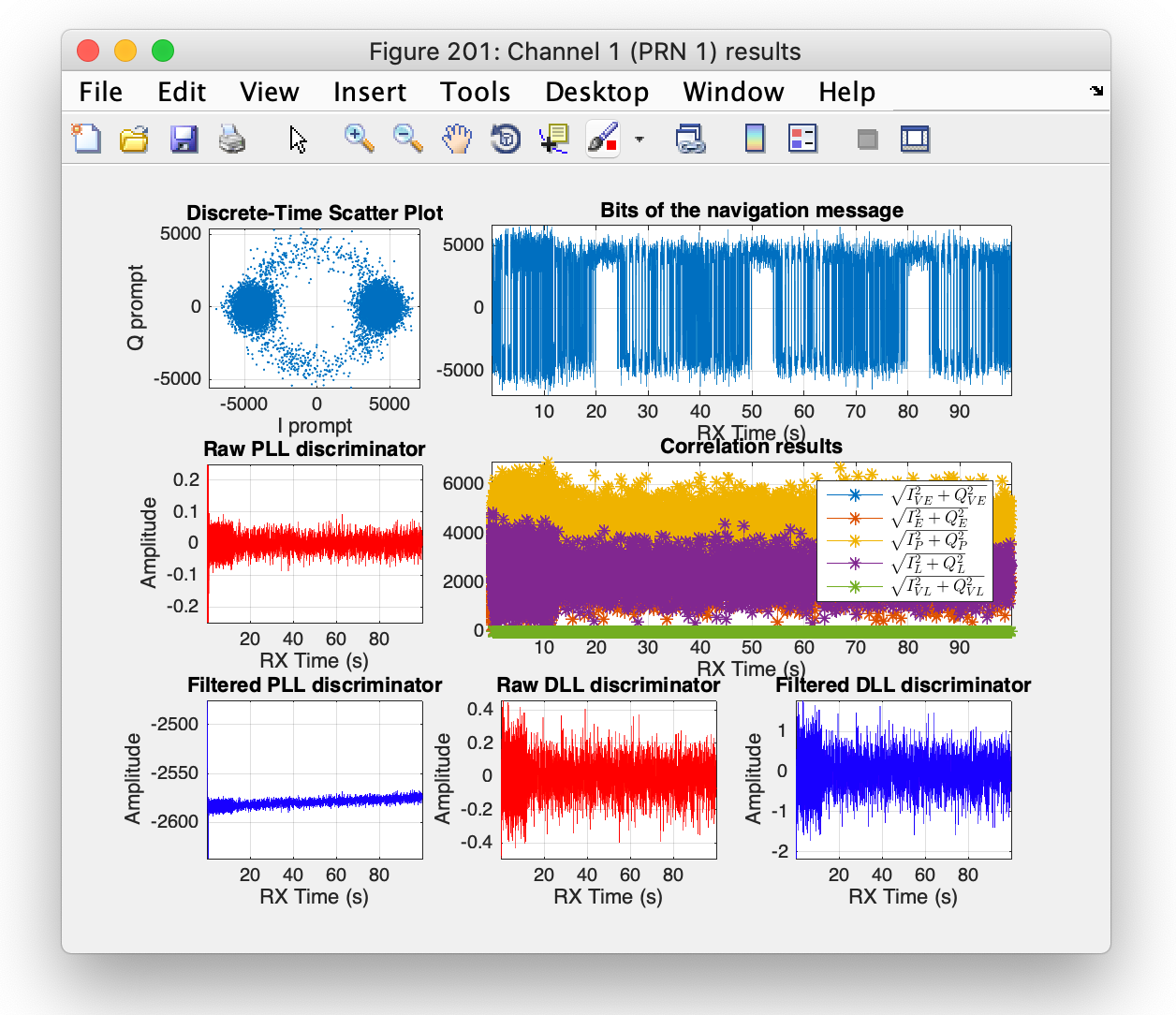 Tracking results for a given channel.
References
-
J. G. Proakis and M. Salehi, Digital Communications, 5th Ed., New York: McGraw-Hill, 2008. ↩
-
D. R. Pauluzzi and N. C. Beaulieu, A comparison of SNR estimation techniques for the AWGN channel, IEEE Transactions on Communications, Vol. 48, no. 10, pp 1681-1691, Oct. 2000. ↩
-
E. D. Kaplan and C. J. Hegarty, Eds., Understanding GPS. Principles and Applications, 3rd edition, Artech House, Norwood, MA, 2017. ↩ ↩2
-
C. Fernández-Prades, J. Arribas, L. Esteve-Elfau, D. Pubill, P. Closas, An Open Source Galileo E1 Software Receiver, in Proceedings of the 6th ESA Workshop on Satellite Navigation Technologies (NAVITEC 2012), 5-7 December 2012, ESTEC, Noordwijk, The Netherlands. ↩
-
M. Petovello, E. Falletti, M. Pini, L. Lo Presti, Are Carrier-to-Noise algorithms equivalent in all situations?. Inside GNSS, Vol. 5, no. 1, pp. 20-27, Jan.-Feb. 2010. ↩
-
A. J. Van Dierendonck, “GPS Receivers”, from Global Positioning System: Theory and Applications, Volume I, Edited by B. W. Parkinson and J. J. Spilker Jr., American Institute of Aeronautics and Astronautics, 1996. ↩