The Control Plane
The Control Plane is in charge of creating a flow graph according to the configuration and then managing the processing blocks. It consists of four main components:
- A configuration mechanism, flexible enough to allow for an indeterminate number of algorithms, implementations, associated parameters, and use cases;
- A GNSS block factory encapsulating the complexity involved in the creation of processing blocks and referring to the newly created object through a common interface, thus allowing the addition of new blocks without changing a single line of code of the client software that makes use of it;
- A GNSS flow graph managing the creation of the processing blocks according to the configuration and connecting them together in a process network implementing the software receiver; and
- A Control Thread managing the whole thing.
Hereafter, we describe how those components are implemented in GNSS-SDR.
The configuration mechanism
Configuration allows users to define in an easy way their own custom receiver by specifying the flow graph (the type of signal source, number of channels, algorithms to be used for each channel and each module, strategies for satellite selection, type of output format, etc.). Since it is difficult to foresee what future module implementations will be needed in terms of configuration, we used a very simple approach that can be extended without a major impact on the code. This can be achieved by simply mapping the names of the variables in the processing blocks with the names of the parameters in the configuration.
Properties are passed around within the program using the
ConfigurationInterface
class. There are two implementations of this interface:
FileConfiguration
and
InMemoryConfiguration.
A
FileConfiguration
object reads the properties (pairs of property name and value) from a file and
stores them internally. On the contrary,
InMemoryConfiguration
does not read from a file; it remains empty after instantiation, and property
values and names are set using the set_property method.
FileConfiguration
is intended to be used in the actual GNSS-SDR application whereas
InMemoryConfiguration
is intended to be used in tests to avoid file-dependency in the file system.
Classes that need to read configuration parameters will receive instances of
ConfigurationInterface
from where they will fetch the values. For instance, parameters related to
SignalSource should look like this:
SignalSource.parameter1=value1
SignalSource.parameter2=value2
The name of these parameters can be anything but one reserved word:
implementation. This parameter indicates in its value the name of the class
that has to be instantiated by the factory for that role. For instance, if we
want to use the implementation Pass_Through for module SignalConditioner,
the corresponding line in the configuration file would be
SignalConditioner.implementation=Pass_Through
Since the configuration is just a set of property names and values without any
meaning or syntax, the system is very versatile and easily extendable. Adding
new properties to the system only implies modifications in the classes that will
make use of these properties. In addition, the configuration files are not
checked against any strict syntax so it is always in a correct status (as long
as it contains pairs of property names and values in
INI format. An INI file is an \(8\)-bit text file in which every property has a name and a value, in the form
name = value. Properties are case-insensitive, and cannot contain spacing
characters. Semicolons (;) indicate the start of a comment; everything between
the semicolon and the end of the line is ignored.
; THIS IS A COMMENT
SignalConditioner.implementation=Pass_Through ; THIS IS ANOTHER COMMENT
In this way, a full GNSS receiver can be uniquely defined in one text file in INI format.
$ gnss-sdr --config_file=/path/to/my_receiver.conf
GNSS-SDR allows the user to define a custom GNSS receiver, including its architecture (number of bands, channels per band, and targeted signal) and the specific algorithms and parameters for each of the processing blocks through a single configuration file (a simple text file in INI format). Thus, each configuration file defines a different GNSS receiver. Some examples of such files are available at gnss-sdr/conf.
The GNSS Block Factory
Hence, the application defines a simple accessor class to fetch the
configuration pairs of values and passes them to a factory class called
GNSSBlockFactory.
This factory decides, according to the configuration, which class needs to be
instantiated and which parameters should be passed to the constructor. Hence,
the factory encapsulates the complexity of blocks’ instantiation. With that
approach, adding a new block that requires new parameters will be as simple as
adding the block class and modifying the factory to be able to instantiate it.
This loose coupling between the blocks’ implementations and the syntax of the
configuration enables extending the application capacities to a high degree. It
also allows producing fully customized receivers (for instance, a testbed for
acquisition algorithms), and to place observers at any point of the receiver
chain.
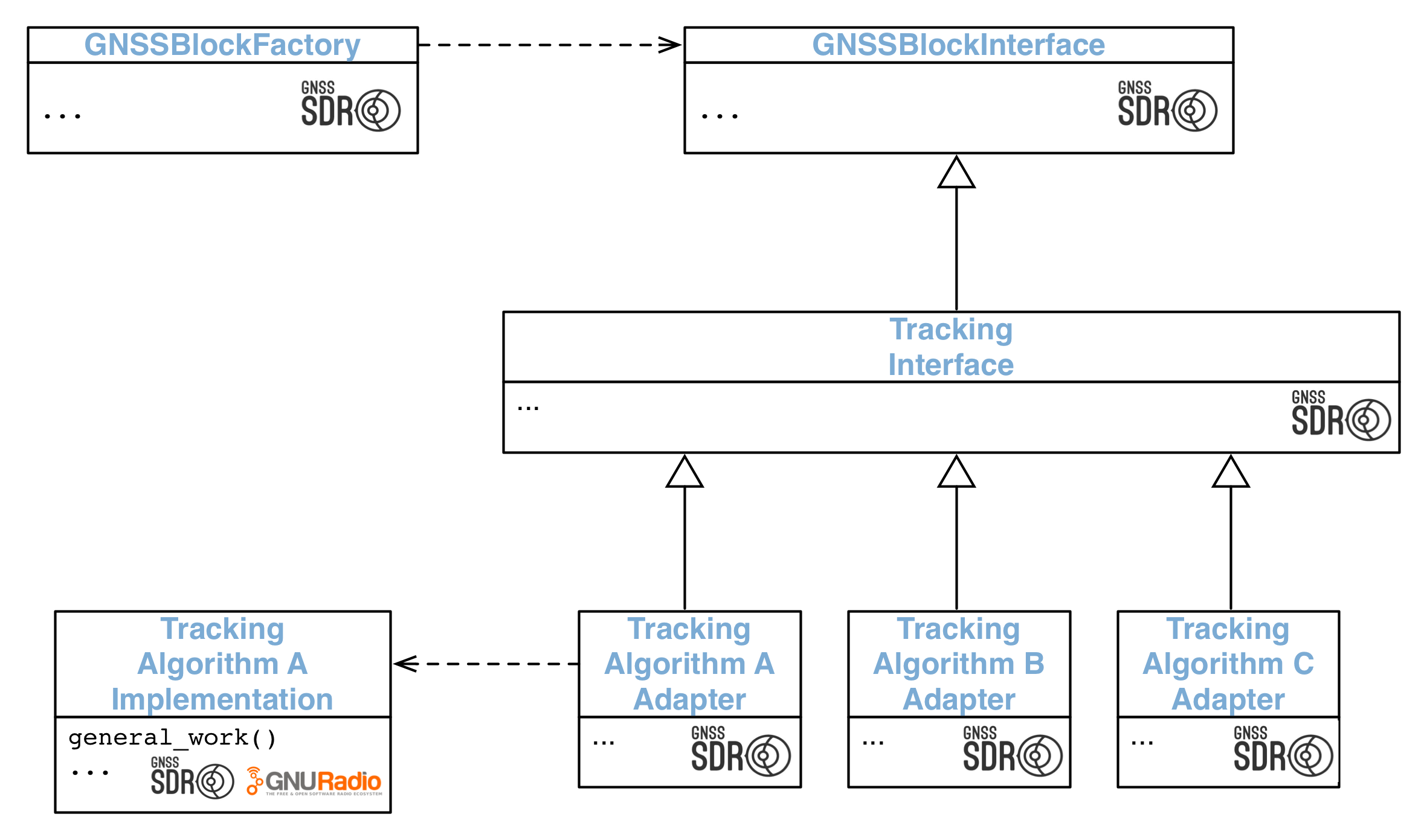 A Factory encapsulates the complexity of the instantiation of processing blocks.
This scheme is known as the Factory Method design pattern1. As shown in the figure above, this pattern encapsulates the processes involved in the creation of objects by defining an interface for creating an object, but letting subclasses decide which class to instantiate.
The GNSS Flow Graph
The
GNSSFlowgraph
class is responsible for preparing the graph of blocks according to the
configuration, running it, modifying it during run-time, and stopping it. Blocks
are identified by their role. This class knows which roles it has to
instantiate, and how to connect them to configure the generic graph that is
shown in the figure below. It relies on the configuration
to get the correct instances of the roles it needs, and then it applies the
connections between GNU Radio blocks to make the graph ready to be started. The
complexity related to managing the blocks and the data stream is handled by GNU
Radio’s
gr::top_block
class.
GNSSFlowgraph
wraps the
gr::top_block
instance so we can take advantage of the GNSS block factory, the configuration
system, and the processing blocks. This class is also responsible for applying
changes to the configuration of the flow graph during run-time, dynamically
reconfiguring channels: it selects the strategy for selecting satellites. This
can range from a sequential search over all the satellites’ ID to smarter
approaches that determine what are the satellites most likely in-view based on
rough estimations of the receiver position in order to avoid searching
satellites on the other side of the Earth.
This class internally codifies actions to be taken on the graph. These actions
are identified by simple integers.
GNSSFlowgraph
offers a method that receives an integer that codifies an action, and this
method triggers the action represented by the integer. Actions can range from
changing internal variables of blocks to modifying completely the constructed
graph by adding/removing blocks. The number and complexity of actions is only
constrained by the number of integers available to make the codification. This
approach encapsulates the complexity of preparing a complete graph with all
necessary blocks instantiated and connected. It also makes good use of the
configuration system and of the GNSS block factory, which keeps the code clean
and easy to understand. It also enables updating the set of actions to be
performed to the graph quite easily.
The Control Thread
The
ControlThread
class is responsible for instantiating the
GNSSFlowgraph
and passing the required configuration. Once the flow graph is defined and its
blocks connected, it starts to process the incoming data stream. The
ControlThread
object is then in charge of reading the control queue and processing all the
messages sent by the processing blocks via a thread-safe message queue.
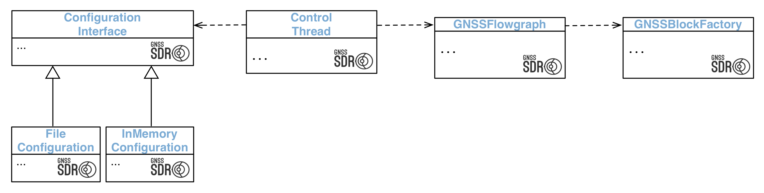 The Control Thread reads the configuration and builds the flow graph of signal processing blocks that defines the receiver.
As we saw in the Overview, the main
method of GNSS-SDR instantiates an object of the class
ControlThread,
managed by a smart pointer:
auto control_thread = std::make_unique<ControlThread>();
The constructor of this object reads the command-line flag provided by the user when executing the receiver which points to the text file containing the configuration, as shown above:
$ gnss-sdr --config_file=/path/to/my_receiver.conf
Then, when the run() method of the control_thread object is called, a member
of class
GNSSFlowgraph
connects the flow graph, starts the flow of data from sources to sinks, and
keeps processing messages from a control queue until the receiver stops.
An excerpt of its actual implementation is as follows, where flowgraph_ is an
object of the class
GNSSFlowgraph:
int ControlThread::run()
{
    // Connect the flowgraph
    flowgraph_->connect();

    // Start the flowgraph
    flowgraph_->start();

    // Launch the GNSS assistance process
    assist_GNSS();

    // Main loop to read and process the control messages
    while (flowgraph_->running() && !stop_)
        {
            read_control_messages();
            if (control_messages_ != 0) process_control_messages();
        }
    std::cout << "Stopping GNSS-SDR, please wait!\n";
    flowgraph_->stop();
    flowgraph_->disconnect();
    return 0;
  }
Hence, the object of class
GNSSFlowgraph
will parse the configuration file and will ask the Block Factory for the
corresponding Signal Source, Signal Conditioner, Channels (each one with its own
Acquisition,
Tracking, and Telemetry
Decoder), one
Observables block
(collecting the processing results from all Channels), and a PVT block (acting as a signal sink):
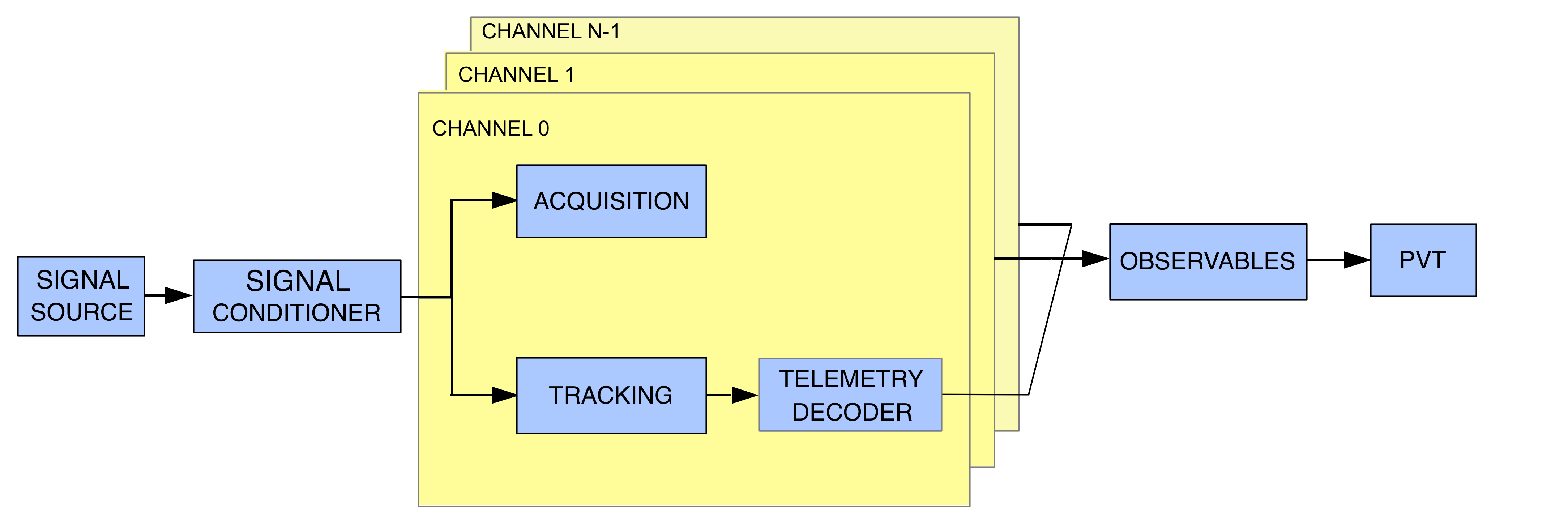 Diagram of a basic (single-band, single-system) flow graph generated by
 GNSSFlowgraph.
Please check out My first position fix for an example of such receiver’s flow graph configuration file.
GNSS-SDR’s configuration mechanism is flexible enough for allowing other more complex flow graphs. For instance, you can target a given signal (for instance, GPS L1 C/A) with eight channels, and define eight more channels targeting Galileo E1 B/C signals, thus defining a multi-system receiver. Or maybe extend that structure to another band, defining a flow graph for a multi-system, dual-band GNSS receiver:
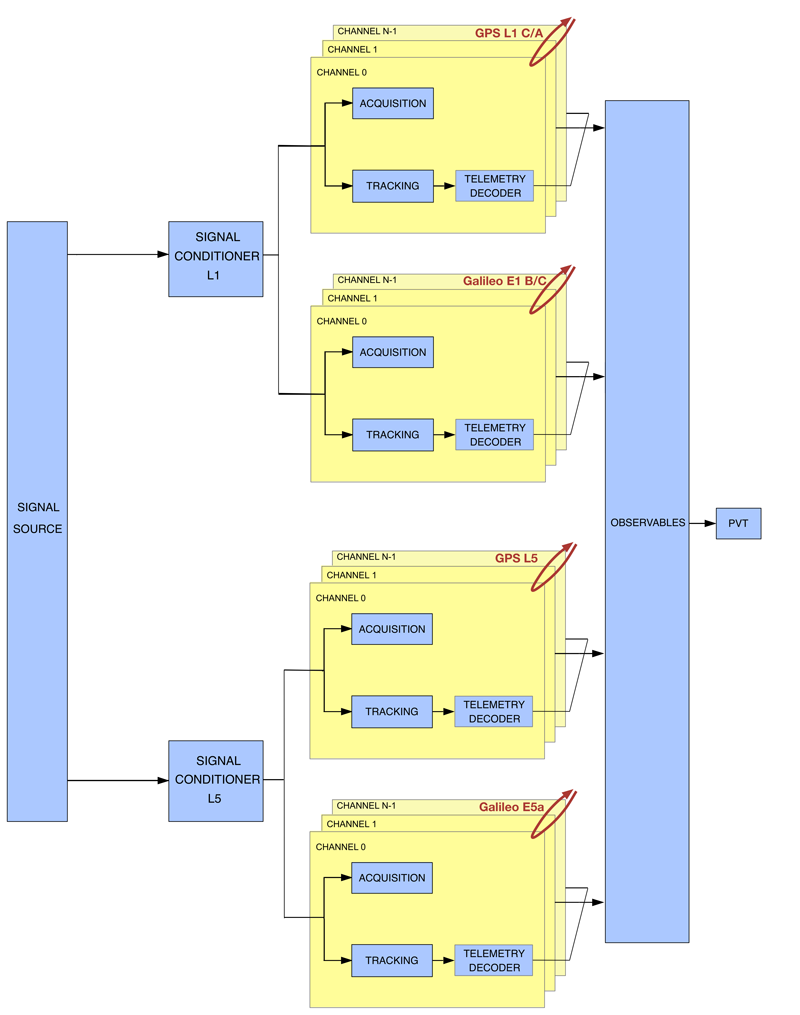 Diagram of a multi-band, multi-system flow graph generated by
 GNSSFlowgraph.
The next section describes the available implementations for each of the available GNSS-SDR processing blocks and how they are configured.
References
-
C. Fernández-Prades, C. Avilés, L. Esteve, J. Arribas and P. Closas, Design patterns for GNSS software receivers, in Proc. of the 5th ESA Workshop on Satellite Navigation Technologies, ESTEC, Noordwijk, The Netherlands, Dec. 2010, pp. 1 - 8. ↩
Leave a comment