GNSS Signals
A generic GNSS complex baseband signal transmitted by a given GNSS space vehicle \(i\) can be described as
\[\begin{equation} \!\!\!\!\!\!\!\!\!\!\!\!s^{(i)}_T(t) = \sqrt{\mathcal{P}_{T}} \sum_{u=-\infty}^{\infty}\Big(d_I^{(i)}(u)g_I(t - uT_{b_I}) + j d_Q^{(i)}(u)g_Q(t - uT_{b_Q})\Big)~, \end{equation}\]where the Inphase and Quadrature (I&Q) components have the form
\[\begin{equation} g(t) = \sum_{k=0}^{N_{c}-1}q(t - kT_{PRN}) \end{equation}\]with
\[\begin{equation} q(t) = \sum_{l=0}^{L_{c}-1}c_{i}(l)p(t - lT_{c}) ~, \end{equation}\]being \(\mathcal{P}_{T}\) the transmitting power, \(d(u)\) the navigation message data symbols, \(T_{b}\) the bit period, \(j\) the imaginary unit, \(N_{c}\) the number of repetitions of a full codeword that spans a bit period, \(T_{PRN}=\frac{T_{b}}{N_{c}}\) the codeword period, \(c_{i}(l)\) a chip of the spreading codeword of length \(L_{c}\) chips corresponding to the space vehicle \(i\), \(p(t)\) the transmitting chip pulse shape, which is considered energy-normalized for notation clarity, and \(T_{c}=\frac{T_{b}}{N_{c} L_{c}}\) the chip period. All parameters can be different in the I and the Q components, there can be uneven power balance among them, and everything will differ in each available frequency band.
This page describes particularizations of such signal structure for all the currently deployed and planned GNSS signals. The notation used in those descriptions is as follows: \(\oplus\) is the exclusive–or operation (modulo–2 addition), \(|l|_{L}\) means \(l\) modulo \(L\), \([l]_{L}\) means the integer part of \(\frac{l}{L}\), and \(p(t)\) is a rectangular pulse of a chip–period duration, filtered at the transmitter at the nominal signal bandwidth and energy-normalized. Links to the official Interface Control Documents are provided in the References section.
Global Positioning System (GPS)
The Navstar Global Positioning System (GPS) is a space-based radio–navigation system owned by the United States Government (USG) and operated by the United States Air Force (USAF). GPS provides positioning and timing services to military and civilian users on a continuous, worldwide basis. Two GPS services are provided:
-
the Precise Positioning Service (PPS)1, available primarily to the military of the United States and its allies, and
-
the Standard Positioning Service (SPS)2, open to civilian users.
The most updated and authorized source is the Official U.S. Government website about GPS and related topics.
GPS L1
Defined in IS-GPS-2003, this band is centered at \(f_{\text{GPS L1}}=1575.42\) MHz. The complex baseband transmitted signal can be written as
\[\begin{equation} s^{\text{(GPS L1)}}_{T}(t) = e_{L1I}(t) + j e_{L1Q}(t)~, \end{equation}\]with
\[\begin{equation} e_{L1I}(t) = \sum_{l=-\infty}^{\infty} D_{\text{NAV}}\Big[ [l]_{204600}\Big] \oplus C_{\text{P(Y)}} \Big[ |l|_{L_{\text{P(Y)}}} \Big] p(t - lT_{c,\text{P(Y)}})~, \end{equation}\] \[\begin{equation} e_{L1Q}(t) = \sum_{l=-\infty}^{\infty} D_{\text{NAV}}\Big[ [l]_{20460}\Big] \oplus C_{\text{C/A}} \Big[ |l|_{1023} \Big] p(t - lT_{c,\text{C/A}})~, \end{equation}\]where \(D_{\text{NAV}} \in \{-1,1\}\) is the GPS navigation message bit sequence, transmitted at \(50\) bit/s, \(T_{c,\text{P(Y)}}=\frac{1}{10.23}\) \(\mu\)s, \(T_{c,\text{C/A}}=\frac{1}{1.023}\) \(\mu\)s, and \(L_{\text{P(Y)}}=6.1871 \cdot 10^{12}\). The precision P codes (named Y codes whenever the anti-spoofing mode is activated, encrypting the code and thus denying non–U.S. military users) are sequences of \(7\) days in length.
Regarding the modernization plans for GPS, it is worthwhile to mention that there is a new civilian–use signal planned, called L1C and defined in IS-GPS-800J4, to be broadcast on the same L1 frequency that currently contains the C/A signal. The L1C signal will be available with first Block III launch, currently scheduled for May 2018 by SpaceX, and it will feature a Multiplexed Binary Offset Carrier (MBOC) modulation scheme that ensures backward compatibility with the C/A signal.
The L1C signal consists of two main components; one denoted \(L1C_P\) to represent a pilot signal, without any data message, that is spread by a ranging code, and \(L1C_D\) that is spread by a ranging code and modulated by a data message. The \(L1C_P\) is also modulated by an SV unique overlay code, \(L1C_O\). The SVs could transmit intentionally “incorrect” versions of the respective ranging codes as needed to protect users from receiving and utilizing anomalous signals. These “incorrect” codes are termed non-standard \(L1C_P\) (NSCP) and non-standard \(L1C_D\) (NSCD). Non-standard codes are not for utilization by the users and, therefore, are not defined in IS-GPS-800J.
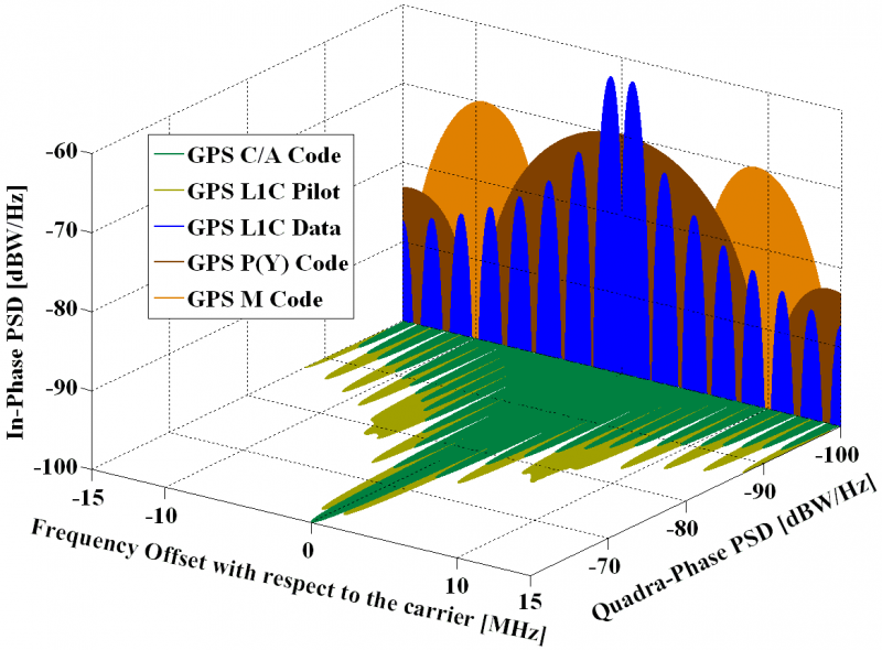 GPS signals spectra in L1. Source: Navipedia.
GPS L2C
Defined in IS-GPS-2003, this band is centered at \(f_{\text{GPS L2}}=1227.60\) MHz. The complex baseband transmitted signal can be written as:
\[\begin{equation} s^{\text{(GPS L2)}}_{T}(t) = e_{L2I}(t) + j e_{L2Q}(t)~, \end{equation}\]with the In-phase component defined as:
\[\begin{equation} e_{L2I}(t) = \sum_{l=-\infty}^{\infty} D_{\text{NAV}}\Big[ [l]_{204600}\Big] \oplus C_{\text{P(Y)}} \Big[ |l|_{L_{\text{P(Y)}}} \Big] p(t - lT_{c,\text{P(Y)}})~, \end{equation}\]with an optional presence of the navigation message \(D_{\text{NAV}}\). For the Quadrature–phase component, three options are defined:
\[\begin{eqnarray} e_{L2Q}(t) & = & \sum_{l=-\infty}^{\infty}\left( D_{\text{CNAV}} \Big[ [l]_{10230} \Big] \oplus C_{\text{CM}} \Big[ |l|_{L_{\text{CM}}} \Big] p_{\text{1/2}} \left(t - lT_{c,L2C} \right) + \right. \nonumber \\ {} & {} & \left. +~C_{\text{CL}} \Big[ |l|_{L_{\text{CL}}} \Big] p_{\text{1/2}}\left(t - \left(l+\frac{1}{2}\right)T_{c,L2C}\right) \right)~, \end{eqnarray}\] \[\begin{equation} e_{L2Q}(t) = \sum_{l=-\infty}^{\infty} D_{\text{NAV}} \Big[ [l]_{20460} \Big] \oplus C_{\text{C/A}} \Big[ |l|_{1023} \Big] p \left(t - lT_{c,\text{C/A}}\right), \end{equation}\]or
\[\begin{equation} e_{L2Q}(t) = \sum_{l=-\infty}^{\infty}C_{\text{C/A}} \Big[ |l|_{1023} \Big] p(t - lT_{c,\text{C/A}})~, \end{equation}\]where \(T_{c,L2C}=\frac{1}{511.5}\) ms and \(p_{\text{1/2}}(t)\) is a rectangular pulse of half chip–period duration, thus time-multiplexing both codes. The civilian long code \(C_{\text{CL}}\) is \(L_{\text{CL}}=767250\) chips long, repeating every \(1.5\) s, while the civilian moderate code \(C_{\text{CM}}\) is \(L_{\text{CM}}=10230\) chips long and it repeats every \(20\) ms. The CNAV data is an upgraded version of the original NAV navigation message, containing higher precision representation and nominally more accurate data than the NAV data. It is transmitted at \(25\) bit/s with forward error correction (FEC) encoding, resulting in \(50\) symbols/s.
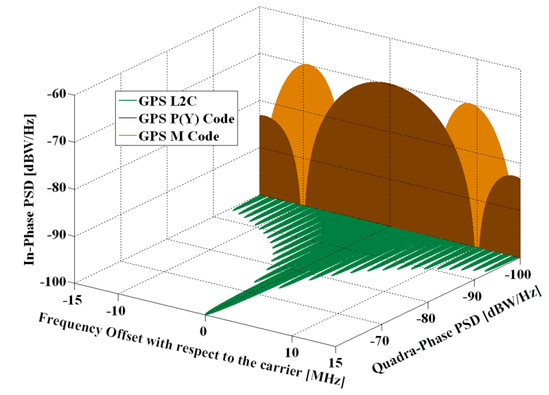 GPS signals spectra in L2. Source: Navipedia.
GPS L2C is only available on Block IIR–M and subsequent satellite blocks.
GPS L5
The GPS L5 link, defined in IS-GPS-7055, is only available on Block IIF and subsequent satellite blocks. Centered at \(f_{\text{GPS L5}}=1176.45\) MHz, this signal in space can be written as:
\[\begin{equation} s^{\text{(GPS L5)}}_{T}(t) = e_{L5I}(t) + j e_{L5Q}(t)~, \end{equation}\] \[\begin{eqnarray} e_{L5I}(t) & = & \sum_{m=-\infty}^{+\infty} C_{nh_{10}} \Big[ |m|_{10}\Big] \oplus D_{\text{CNAV}}\Big[ [m]_{10}\Big] \oplus \nonumber \\ {} & {} & \oplus~\sum_{l=1}^{102300} C_{L5I}\Big[|l|_{10230}\Big] \cdot p(t - m T_{c,nh} - lT_{c,L5}) ~, \end{eqnarray}\] \[\!\!\!\!\!\!\!\!\!\begin{equation} e_{L5Q}(t) = \!\!\sum_{m=-\infty}^{+\infty}\!\! C_{nh_{20}} \Big[ |m|_{20}\Big] \oplus \!\!\sum_{l=1}^{102300}\!\!C_{L5Q}\Big[|l|_{10230}\Big] \! \cdot\! p(t \! - \! m T_{c,nh} \! - \! lT_{c,L5})~, \end{equation}\]where \(T_{c,nh}=1\) ms and \(T_{c,L5}=\frac{1}{10.23}\) \(\mu\)s. The L5I component contains a synchronization sequence \(C_{nh_{10}}=0000110101\), a \(10\)–bit Neuman–Hoffman code that modulates each \(100\) symbols of the GPS L5 civil navigation data \(D_{\text{CNAV}}\), and the L5Q component has another synchronization sequence \(C_{nh_{20}}=00000100110101001110\).
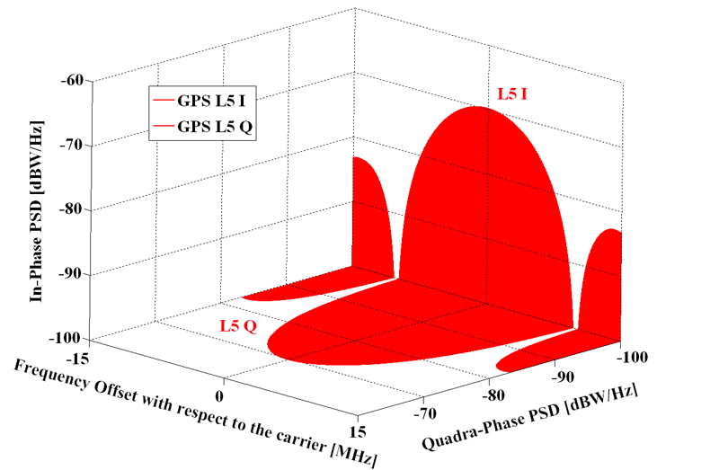 GPS signals spectra in L5. Source: Navipedia.
GLONASS
The nominal baseline constellation of the Russian Federation’s Global Navigation Satellite System (GLONASS) comprises \(24\) GLONASS–M satellites that are uniformly deployed in three roughly circular orbital planes at an inclination of \(64.8^o\) to the equator. The altitude of the orbit is \(19,100\) km. The orbit period of each satellite is \(11\) hours, \(15\) minutes, and \(45\) seconds. The orbital planes are separated by \(120^o\) right ascension of the ascending node. Eight satellites are equally spaced in each plane with \(45^o\) argument of latitude. Moreover, the orbital planes have an argument of latitude displacement of \(15^o\) relative to each other. The current constellation status can be checked at the Russian Information and Analysis Center for Positioning, Navigation and Timing website.
The ground control segment of GLONASS is almost entirely located within former Soviet Union territory, except for a station in Brasilia, Brazil. The Ground Control Center and Time Standards is located in Moscow and the telemetry and tracking stations are in Saint Petersburg, Ternopol, Eniseisk, and Komsomolsk-na-Amure.
GLONASS civil signal–in–space is defined in GLONASS’ ICD 6. This system makes use of a frequency–division multiple access (FDMA) signal structure, transmitting in two bands:
- \(f^{(k)}_{GLO L1}=1602+k \cdot 0.5625\) MHz and
- \(f^{(k)}_{GLO L2}=1246+k \cdot 0.4375\) MHz,
where \(k\in \left\{ -7,-6,\cdots,5,6\right\}\) is the channel number. Satellites in opposite points of an orbit plane transmit signals on equal frequencies, as these satellites will never be in view simultaneously by a ground-based user.
The modernization of GLONASS includes the adoption of the CDMA scheme7, with new open signals called L1OC, L2OC, and L3OC.
GLONASS L1
Two kinds of signals are transmitted: a standard precision (SP) and an obfuscated high precision (HP) signal. The complex baseband transmitted signal can be written as
\[\begin{equation} s^{\text{(GLO L1)}}_{T}(t) = e_{L1I}(t) + j e_{L1Q}(t)~, \end{equation}\]with
\[\begin{equation} e_{L1I}(t) = \sum_{l=-\infty}^{\infty} D_{\text{GNAV}}\Big[ [l]_{102200}\Big] \oplus C_{\text{HP}} \Big[ |l|_{L_{\text{HP}}} \Big] p(t - lT_{c,\text{HP}})~, \end{equation}\] \[\begin{equation} e_{L1Q}(t) = \sum_{l=-\infty}^{\infty} D_{\text{GNAV}}\Big[ [l]_{10220} \Big] \oplus C_{\text{SP}} \Big[ |l|_{511} \Big] p(t - lT_{c,\text{SP}})~, \end{equation}\]where \(T_{c,\text{HP}}=\frac{1}{5.11}\) \(\mu\)s, \(T_{c,\text{SP}}=\frac{1}{0.511}\) \(\mu\)s, and \(L_{\text{HP}}=3.3554\cdot 10^7\). The navigation message \(D_{\text{GNAV}}\) is transmitted at \(50\) bit/s. Details of its content and structure, as well as the generation of the \(C_{\text{SP}}\) code, can be found in GLONASS’ ICD 6. The usage of the HP signal should be agreed upon with the Russian Federation Defense Ministry, and no more details have been disclosed.
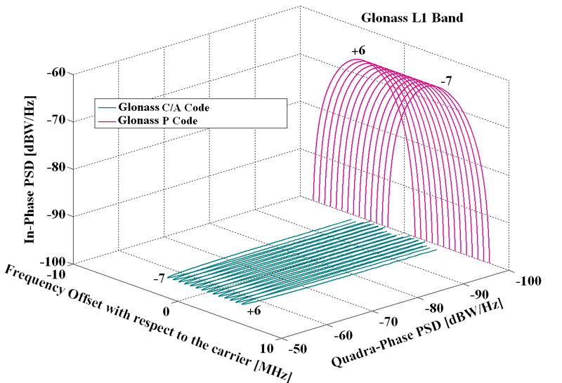 GLONASS signals spectra in L1. Source: Navipedia.
The use of FDMA techniques, in which the same code is used to broadcast navigation signals on different frequencies, and the placement of civil GLONASS transmissions on frequencies centered at \(1602\) MHz, well above the GPS L1 band, have complicated the design of combined GLONASS/GPS receivers, particularly low–cost equipment for mass-market applications.
In late 2016, the Russian Federation published a new ICD related to a CDMA signal at \(1600.99\) MHz, referred to as L1OC, to be broadcast by GLONASS satellites starting by Enhanced Glonass-K1 and Glonass-K2, launched from 2018. This documentation is only available in Russian 8.
GLONASS L2
Beginning with the second generation of satellites, called GLONASS–M and first launched in 2001, a second civil signal is available using the same SP code as the one in the L1 band but centered at \(1246\) MHz.
 GLONASS signals spectra in L2. Source: Navipedia.
Future plans of modernization are intended to increase compatibility and interoperability with other GNSS, and include the addition of a code-division multiple access (CDMA) structure.
On July 2, 2013, a Russian Proton-M rocket carrying three GLONASS–M navigation satellites crashed soon after liftoff today from Kazakhstan’ Baikonur cosmodrome.
In late 2016, the Russian Federation published a new ICD related to a CDMA signal at \(1248.06\) MHz, referred to as L2OC and featuring a BOC(1,1) modulation, to be broadcast by GLONASS satellites starting by Enhanced Glonass-K1 and Glonass-K2, to be launched from 2018. This documentation is only available in Russian 9.
GLONASS L3
In late 2016, the Russian Federation published a new ICD related to a CDMA signal at \(1202.025\) MHz, referred to as L3OC and featuring a BPSK(10) modulation, to be broadcast by GLONASS satellites starting by Glonass-M, in production since 2014. This documentation is only available in Russian 10.
Galileo
The nominal Galileo constellation comprises a total of \(24\) operational satellites (plus \(6\) active spares), that are evenly distributed among three orbital planes inclined at \(56^o\) relative to the equator. There are eight operational satellites per orbital plane, occupying evenly distributed orbital slots. Six additional spare satellites (two per orbital plane) complement the nominal constellation configuration. The Galileo satellites are placed in quasi-circular Earth orbits with a nominal semi-major axis of about \(30,000\) km and an approximate revolution period of \(14\) hours. The Control segment full infrastructure will be composed of \(30-40\) sensor stations, \(3\) control centers, \(9\) Mission Uplink stations, and \(5\) TT&C stations. The current constellation status can be checked at the European GNSS Service Centre website.
Galileo’s Open Service is defined in the Service Definition Document (SDD)11, and the corresponding signal structures are defined in the Interface Control Document (ICD)12. In this latter document, the following signal structures are specified:
Galileo E1
This band, centered at \(f_{\text{Gal E1}}=1575.420\) MHz and with a reference bandwidth of \(24.5520\) MHz, uses the Composite Binary Offset Carrier (CBOC) modulation, defined in baseband as:
\[\begin{eqnarray} s^{\text{(Gal E1)}}_{T}(t) & = & \frac{1}{\sqrt{2}} \Big( e_{E1B}(t)\left(\alpha sc_A(t) + \beta sc_B(t) \right) + \nonumber \\ {} & {} & -~e_{E1C}(t) \left(\alpha sc_A(t) - \beta sc_B(t) \right) \Big)~, \end{eqnarray}\]where the subcarriers \(sc(t)\) are defined as
\[\begin{equation} sc_A(t) = \text{sign} \Big(\sin(2\pi f_{sc,E1A}t) \Big)~, \end{equation}\] \[\begin{equation} sc_B(t) = \text{sign} \Big(\sin(2\pi f_{sc,E1B}t) \Big)~, \end{equation}\]and \(f_{sc,E1A}=1.023\) MHz, \(f_{sc,E1B}=6.138\) MHz are the subcarrier rates, \(\alpha=\sqrt{\frac{10}{11}}\), and \(\beta=\sqrt{\frac{1}{11}}\). Channel B contains the I/NAV type of navigation message, \(D_{I/NAV}\), intended for Safety–of–Life (SoL) services:
\[\begin{equation} e_{E1B}(t) = \sum_{l=-\infty}^{+\infty} D_{\text{I/NAV}} \Big[ [l]_{4092}\Big] \oplus C_{E1B}\Big[|l|_{4092}\Big] p(t - lT_{c,E1B})~. \end{equation}\]In the case of channel C, it is a pilot (dataless) channel with a secondary code, forming a tiered code:
\[\!\!\!\!\!\!\!\!\!\!\begin{equation} e_{E1C}(t) \! = \!\! \sum_{m=-\infty}^{+\infty} \! C_{E1Cs}\Big[|m|_{25}\Big] \! \oplus \! \sum_{l=1}^{4092} \! C_{E1Cp}\Big[ l \Big] \! \cdot \! p(t \! - \! mT_{c,E1Cs} \! - \! lT_{c,E1Cp})~, \end{equation}\]with \(T_{c,E1B}=T_{c,E1Cp}=\frac{1}{1.023}\) \(\mu\)s and \(T_{c,E1Cs}=4\) ms. The \(C_{E1B}\) and \(C_{E1Cp}\) primary codes are pseudorandom memory code sequences defined in Galileo’s ICD12 [Annex C]. The binary sequence of the secondary code \(C_{E1Cs}\) is \(0011100000001010110110010\). This band also contains another component, Galileo E1A, intended for the Public Regulated Service (PRS), that uses a BOC modulation with cosine–shaped subcarrier, \(f_{sc,E1A}=15.345\) MHz, and \(T_{c,E1A}=\frac{1}{2.5575}\) \(\mu\)s. The PRS spreading codes and the structure of the navigation message have not been made public.
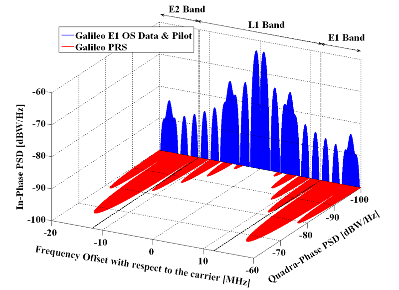 Galileo signals spectra in E1. Source: Navipedia.
Galileo E6
Galileo will provide users with added-value services offered through the E6 band, namely:
- The Galileo High Accuracy Service (HAS) will allow users to obtain a positioning error below two decimeters in nominal conditions of use, worldwide. The Galileo HAS will be based on the free transmission of Precise Point Positioning (PPP) corrections through the Galileo E6 signal data component \(e_{E6B}(t)\) by the Galileo satellites.
- The Galileo Commercial Authentication Service (CAS) will make it possible to authenticate signals, allowing for increased robustness of professional applications by giving access to the E6 signal pilot component \(e_{E6C}(t)\) codes, which will be encrypted.
This signal, which is centered at \(f_{\text{Gal E6}}=1278.750\) MHz, has a pilot and a data component:
\[\begin{equation} s_{T}^{\text{(Gal E6)}}(t) = \frac{1}{\sqrt{2}}\left(e_{E6B}(t) - e_{E6C}(t)\right)~, \end{equation}\] \[\begin{equation} e_{E6B}(t) = \sum_{m=-\infty}^{+\infty} D_{\text{HAS}} \Big[ [m]_{5115}\Big] \oplus C_{E6B}\Big[|m|_{5115}\Big] \cdot p(t - mT_{c,E6B})~, \end{equation}\] \[\!\!\!\!\!\!\!\!\!\begin{equation} e_{E6C}(t) \! = \!\!\! \sum_{m=-\infty}^{+\infty} \! C_{E6Cs}\Big[|m|_{100}\Big] \! \oplus \! \sum_{l=1}^{L_{E6C}} \!\! C_{E6Cp}\Big[ l \Big]\! \cdot \! p(t \! - \! mT_{c,E6Cs} \! - \! lT_{c,E6Cp}), \end{equation}\]where \(D_{\text{HAS}}\) is the HAS navigation data stream, which is modulated with the ranging code \(C_{E6B}\) with chip period \(T_{c,E6B}=\frac{1}{5.115}\) \(\mu\)s. Codes \(C_{E6B}\), \(C_{E6Cp}\) and \(C_{E6Cs}\) are published in Galileo’s E6-B/C Codes Technical Note13, and the HAS message structure is described in the Galileo High Accuracy Service Signal-In-Space Interface Control Document (HAS SIS ICD)14.
This band also contains another component, Galileo E6A, intended for the Public Regulated Service (PRS). It uses a BOC modulation with cosine–shaped subcarrier, \(f_{sc,E6A}=10.23\) MHz, and \(T_{c, E6A}=\frac{1}{5.115}\) \(\mu\)s. The PRS spreading codes and the structure of the navigation message are not publicly available.
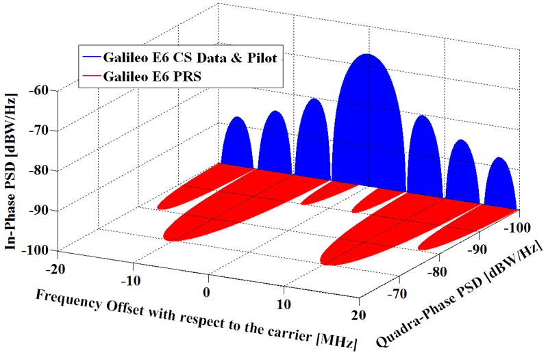 Galileo signals spectra in E6. Source: Navipedia.
Galileo E5
Centered at \(f_{\text{Gal E5}}=1191.795\) MHz and with a total (baseband) bandwidth of \(51.150\) MHz, its signal structure deserves some analysis. The AltBOC modulation can be generically expressed as
\[\begin{equation} s^{\text{AltBOC}}(t) = x_1(t)v^{*}(t) + x_2(t)v(t)~, \end{equation}\]where \(v(t)=\frac{1}{\sqrt{2}}\left( \text{sign}\left( \cos (2 \pi f_{sc,E5} t)\right)+j \text{sign}\left( \sin (2 \pi f_{sc,E5} t)\right)\right)\) is the single side-band subcarrier, \(f_{sc,E5}\) is the subcarrier frequency, \((\cdot)^{*}\) stands for the conjugate operation, and \(x_1(t)\) and \(x_2(t)\) are QPSK signals. The resulting waveform does not exhibit a constant envelope. In the case of Galileo, the need for high efficiency of the satellites’ onboard High Power Amplifier (HPA) has pushed a modification on the signal in order to make it envelope-constant and thus use the HPA at saturation. This can be done by adding some inter-modulation products to the expression above, coming up with the following definition:
\[\begin{eqnarray} s^{\text{(Gal E5)}}_{T}(t) & = & e_{E5a}(t) ssc_s^{*}(t)+ e_{E5b}(t)ssc_s(t) + \nonumber \\ {} & {} & +~\bar{e}_{E5a}(t)ssc_p^{*}(t)+\bar{e}_{E5b}(t)ssc_p(t)~, \end{eqnarray}\]where the single and product side-band signal subcarriers are
\[\begin{equation} ssc_s(t) = sc_s(t) +jsc_s\left(t-\frac{T_s}{4}\right) ~, \end{equation}\] \[\begin{equation} ssc_p(t) = sc_p(t) +jsc_p\left(t-\frac{T_s}{4}\right) ~, \end{equation}\]and
\[\begin{equation} e_{E5a}(t) = e_{E5aI}(t)+je_{E5aQ}(t)~, \end{equation}\] \[\begin{equation} e_{E5b}(t) = e_{E5bI}(t)+je_{E5bQ}(t)~, \end{equation}\] \[\begin{equation} \bar{e}_{E5a}(t) = \bar{e}_{E5aI}(t)+j\bar{e}_{E5aQ}(t)~, \end{equation}\] \[\begin{equation} \bar{e}_{E5b}(t) = \bar{e}_{E5bI}(t)+j\bar{e}_{E5bQ}(t)~, \end{equation}\] \[\begin{equation} \bar{e}_{E5aI}(t) = e_{E5aQ}(t)e_{E5bI}(t)e_{E5bQ}(t)~, \end{equation}\] \[\begin{equation} \bar{e}_{E5aQ}(t) = e_{E5aI}(t)e_{E5bI}(t)e_{E5bQ}(t)~, \end{equation}\] \[\begin{equation} \bar{e}_{E5bI}(t) = e_{E5bQ}(t)e_{E5aI}(t)e_{E5aQ}(t)~, \end{equation}\] \[\begin{equation} \bar{e}_{E5bQ}(t) = e_{E5bI}(t)e_{E5aI}(t)e_{E5aQ}(t). \end{equation}\]The signal components are defined as
\[\begin{eqnarray} e_{E5aI}(t) & = & \sum_{m=-\infty}^{+\infty}C_{E5aIs}\Big[|m|_{20}\Big] \oplus \sum_{l=1}^{10230}C_{E5aIp}\Big[ l \Big] \oplus \nonumber \\ {} & {} & \oplus~D_{\text{F/NAV}} \Big[ [l]_{204600}\Big] p(t-mT_{c,E5s}-lT_{c,E5p})~, \end{eqnarray}\] \[\begin{eqnarray} e_{E5aQ}(t) & = & \sum_{m=-\infty}^{+\infty}C_{E5aQs}\Big[|m|_{100}\Big] \oplus \sum_{l=1}^{10230}C_{E5aQp}\Big[ l \Big] \cdot\nonumber \\ {} & {} & \cdot~p(t-mT_{c,E5s}-lT_{c,E5p})~, \end{eqnarray}\] \[\begin{eqnarray} e_{E5bI}(t) & = & \sum_{m=-\infty}^{+\infty}C_{E5bIs}\Big[|m|_{4}\Big] \oplus \sum_{l=1}^{10230}C_{E5aIp}\Big[ l \Big] \oplus \nonumber \\ {} & {} & \oplus~D_{\text{I/NAV}} \Big[ [l]_{40920}\Big] p(t-mT_{c,E5s}-lT_{c,E5p})~, \end{eqnarray}\] \[\begin{eqnarray} e_{E5bQ}(t) & = & \sum_{m=-\infty}^{+\infty}C_{E5bQs}\Big[|m|_{100}\Big] \oplus \sum_{l=1}^{10230}C_{E5bQp}\Big[ l \Big] \cdot\nonumber \\ {} & {} & \cdot~p(t-mT_{c,E5s}-lT_{c,E5p})~, \end{eqnarray}\]where \(T_{c,E5s}=1\) ms and \(T_{c,E5p}=\frac{1}{10.23}\) \(\mu\)s. Channel A contains the F/NAV type of navigation message, \(D_{F/NAV}\), intended for the Open Service. The I/NAV message structures for the E5bI and E1B signals use the same page layout. Only page sequencing is different, with page swapping between both components in order to allow a fast reception of data by a dual-frequency receiver. The single subcarrier \(sc_s(t)\) and the product subcarrier \(sc_p(t)\) are defined as:
\[\begin{eqnarray} \!\!\!\!\! sc_s(t) & = & \frac{\sqrt{2}}{4}\text{sign} \left( \cos \left( 2 \pi f_{sc,E5} t - \frac{\pi}{4}\right) \right)+\frac{1}{2}\text{sign} \Big( \cos \left( 2 \pi f_{sc,E5} t \right) \Big)+ \nonumber \\ {} & {} & + \frac{\sqrt{2}}{4}\text{sign} \left( \cos \left( 2 \pi f_{sc,E5} t + \frac{\pi}{4}\right) \right)~, \end{eqnarray}\] \[\begin{eqnarray} \!\!\!\!\!\!\!\!\!\!sc_p(t) & = & -\frac{\sqrt{2}}{4}\text{sign} \left( \cos \left( 2 \pi f_{sc,E5} t - \frac{\pi}{4}\right) \right)+ \frac{1}{2}\text{sign} \Big( \cos \left( 2 \pi f_{sc,E5} t \right) \Big)+\nonumber \\ {} & {} & -\frac{\sqrt{2}}{4}\text{sign} \left( \cos \left( 2 \pi f_{sc,E5} t + \frac{\pi}{4}\right) \right)~, \end{eqnarray}\]with a subcarrier frequency of \(f_{sc,E5} = 15.345\) MHz.
Plotting the power spectrum of the carriers for \(s^{\text{(Gal E5)}}_{T}(t)\) (see Figure below), we can see that the QPSK signal \(e_{E5a}(t)\) defined above is shifted to \(f_{\text{Gal E5a}} \doteq f_{\text{Gal E5}} - f_{sc,E5} = 1176.450\) MHz, while \(e_{E5b}(t)\) is shifted to \(f_{Gal E5b} \doteq f_{\text{Gal E5}} + f_{sc,E5} = 1207.140\) MHz.
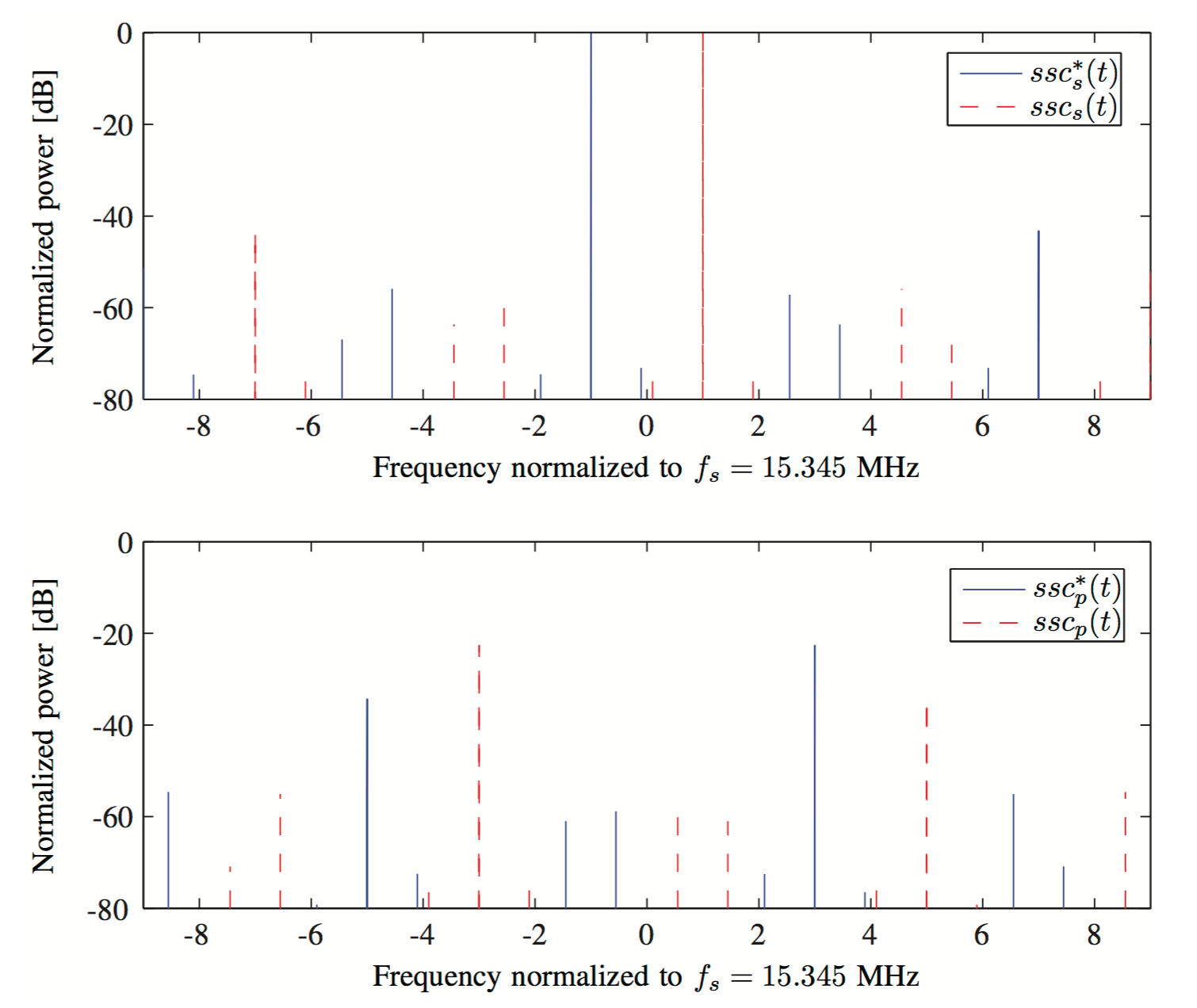 Power spectrum of single and product side-band subcarriers signals for \(s^{\text{(Gal E5)}}_{T}(t)\), normalized to the power of \(ssc^{*}_s(t)\) at \(f_{\text{Gal E5a}}\). The modified AltBOC modulation can be well approximated
by two QPSK signals \(2 f_{sc,E5}\) apart, with negligible contribution of the
crossed terms around its center frequency.15
Power spectrum of single and product side-band subcarriers signals for \(s^{\text{(Gal E5)}}_{T}(t)\), normalized to the power of \(ssc^{*}_s(t)\) at \(f_{\text{Gal E5a}}\). The modified AltBOC modulation can be well approximated
by two QPSK signals \(2 f_{sc,E5}\) apart, with negligible contribution of the
crossed terms around its center frequency.15
Thus, we can bandpass filter around \(f_{Gal E5a}\) and get a good approximation of a QPSK signal, with very low energy components of \(e_{E5b}(t)\), \(\bar{e}_{E5a}(t)\), and \(\bar{e}_{E5b}(t)\):
\[\begin{equation} s_{T}^{(Gal E5a)}(t) \simeq e_{E5aI}(t)+je_{E5aQ}(t). \end{equation}\]The same applies to \(e_{E5b}(t)\), allowing an independent reception of two QPSK signals and thus requiring considerably less bandwidth than the processing of the whole E5 band.
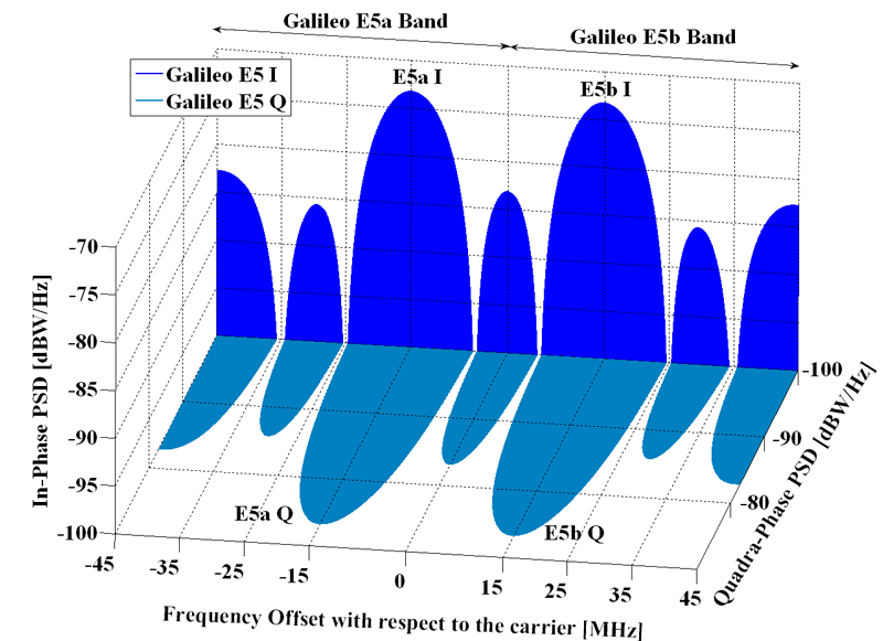 Galileo signals spectra in E5. Source: Navipedia.
BeiDou
People’s Republic of China was also concerned with the importance of an accurate (and independent) navigation and timing satellite system.
According to the China National Space Administration, in a communicate dated on May 19, 2010, the development of the system would be carried out in three steps:
- 2000 – 2003: China built the BeiDou Satellite Navigation Experimental System, also known as BeiDou-1, consisting of 3 satellites. It offered limited coverage and applications and nowadays is not usable.
- by 2012: regional BeiDou navigation system covering China and neighboring regions.
- by 2020: global BeiDou navigation system.
The second generation of the system, officially called the BeiDou Satellite Navigation System (BDS) and also formerly known as COMPASS or BeiDou-2, will be a global satellite navigation system consisting of \(5\) geostationary satellites and \(30\) non–geostationary satellites. The geostationary satellites will be located at \(58.75^o\) E, \(80^o\) E, \(110.5^o\) E, \(140^o\) E and \(160^o\) E. Non–geostationary satellites will be in medium–Earth orbit (MEO) and inclined geosynchronous orbit. Global coverage is planned by 2020. The ground segment will consist of one Master Control Station, two Upload Stations and \(30\) Monitor Stations.
After the first geostationary satellite (located at \(140^o\) E) was launched on October 31, 2000, a second satellite (located at \(80^o\) E) and a third satellite (located at \(110.5^o\) E) were launched on December 21, 2000, and May 25, 2003, respectively. The first geostationary satellite, COMPASS–G2, was launched on April 15, 2009.
On December 27, 2012, the Chinese government released the first version of BeiDou’s Interface Control Document (ICD), a 77-page document that included details of the navigation message, including parameters of the satellite almanacs and ephemerides that were missing from a “test version” of the ICD released exactly one year before. One year later version 2.0 was released, version 2.1 followed in November 201616, and version 3.0 in February 201917. Starting 2018, version 1.0 of the ICD for B1C18, B2a19 and B3I20 signals were released, describing the open services deployed in the BSD-3 phase of the system development.
![]() On December 2012, the China Satellite Navigation Office released the
official logo of the BeiDou system, the design of which incorporates the
yin/yang symbol reflecting traditional Chinese culture, dark and light
blue coloration symbolizing, respectively, space and Earth (including
the aerospace industry), and the Big Dipper (a pattern of stars
recognized on Earth’s night sky which star components are the seven
brightest of the constellation Ursa Major) used for navigation since
ancient times to locate the North Star Polaris and representing the
first navigation device developed by China.
On December 2012, the China Satellite Navigation Office released the
official logo of the BeiDou system, the design of which incorporates the
yin/yang symbol reflecting traditional Chinese culture, dark and light
blue coloration symbolizing, respectively, space and Earth (including
the aerospace industry), and the Big Dipper (a pattern of stars
recognized on Earth’s night sky which star components are the seven
brightest of the constellation Ursa Major) used for navigation since
ancient times to locate the North Star Polaris and representing the
first navigation device developed by China.
It also appeared that China intended to discontinue the use of COMPASS as the English name for BeiDou. During the press briefing about the publication of the ICD, Ran Chengqi, director of China Satellite Navigation Office, said the English designation will henceforth be BeiDou Navigation Satellite System with the abbreviation BDS.
Updated information can be found at the Beidou Navigation Satellite System website. The status of the constellation can be consulted here.
Beidou B1I
BeiDou B1 transmitted by BDS-2 satellites is centered at \(f_{B1} = 1561.098\) MHz, featuring a QPSK(2) modulation. The complex baseband transmitted signal can be written as:
\[\begin{equation} s^{\text{(BeiDou B1)}}_{T}(t) = e_{B1I}(t) + j e_{B1Q}(t)~, \end{equation}\]with
\[\begin{equation} e_{B1I}(t) = \sum_{l=-\infty}^{\infty} D_{\text{NAV}}\Big[ [l]_{40920}\Big] \oplus C_{\text{B1I}} \Big[ |l|_{2046} \Big] p(t - lT_{c,\text{B1I}})~, \end{equation}\] \[\begin{equation} e_{B1Q}(t) = \sum_{l=-\infty}^{\infty} D_{\text{NAV}}\Big[ [l]_{\text{N/A}}\Big] \oplus C_{\text{B1Q}} \Big[ |l|_{L_{\text{B1Q}}} \Big] p(t - lT_{c,\text{B1Q}})~, \end{equation}\]Beidou’s Interface Control Document version 3.0 describes the Inphase-component of the Beidou B1 link.17 The chip rate of the B1I ranging code, \(C_{B1I}\) is 2.046 Mcps, and the length is 2046 chips.
The B1I signal is also transmitted by all satellites of BDS-3.
BeiDou B1C
BeiDou Open Service B1C signals, transmitted by Medium Earth Orbit (MEO) satellites and the Inclined GeoSynchronous Orbit (IGSO) satellites of BDS-3, are centered at \(f_{B1C} = 1575.42\) MHz and feature a BOC(1,1) modulation in the data component and a QMBOC(6, 1, 4/33) modulation in the pilot component. The complex baseband transmitted signal can be written as:18
\[\begin{equation} s^{\text{(BeiDou B1C)}}_{T}(t) = e_{B1C\_data}(t) + j e_{B1C\_pilot}(t)~, \end{equation}\]with
\[\begin{eqnarray} e_{B1C\_data}(t) & = & \frac{1}{2} \sum_{l=-\infty}^{\infty} D_{\text{B-CNAV1}}\Big[ [l]_{10230}\Big] \oplus \nonumber \\ {} & {} & \oplus~C_{B1C\_data} \Big[ |l|_{10230} \Big] p(t - lT_{c,B1C\_data}) sc_{B1C\_data}(t)~, \end{eqnarray}\] \[\begin{eqnarray} e_{B1C\_pilot}(t) & = & \frac{\sqrt{3}}{2} \sum_{l=-\infty}^{\infty} \Big[ [l]_{10230} \Big] \oplus \nonumber \\ {} & {} & \oplus~C_{B1C\_pilot} \Big[ |l|_{10230} \Big] p(t - lT_{c,B1C\_pilot})sc_{B1C\_pilot}(t)~, \end{eqnarray}\]where:
\[\begin{equation} sc_{B1C\_data}(t) = \text{sign} \left(\sin \left(2 \pi f_{sc\_B1C\_a} t \right) \right)~, \end{equation}\] \[\begin{eqnarray} sc_{B1C\_pilot}(t) & = & \sqrt{\frac{29}{33}} \text{sign} \left(\sin \left(2 \pi f_{sc\_B1C\_a} t \right) \right) + \nonumber \\ {} & {} & - j \sqrt{\frac{4}{33}} \text{sign} \left(\sin \left(2 \pi f_{sc\_B1C\_b} t \right) \right)~ , \end{eqnarray}\]with \(f_{sc\_B1C\_a} = 1.023\) MHz and \(f_{sc\_B1C\_b} = 6.138\) MHz. The code length of the ranging codes \(C_{B1C\_data}\) and \(C_{B1C\_pilot}\) is 10230 chips, and \(T_{c,B1C\_data} = T_{c,B1C\_pilot} = \frac{1}{1.023}\) \(\mu\)s. Both of data and pilot ranging codes are tired codes composed of primary and secondary codes. For both data and pilot channels, the primary and secondary codes are generated from Weil sequences, and the starting boundaries of the primary and secondary codes are strictly synchronized. The navigation message \(D_{\text{B-CNAV1}}\) has a symbol rate of 100 bit/s.
Since \(e_{B1C\_pilot}(t)\) is a complex waveform, the B1C signal contains three components as shown in the following equation:
\[\begin{equation} s^{\text{(BeiDou B1C)}}_{T}(t) = e_{B1C\_data}(t) + e_{B1C\_pilot\_b}(t) + je_{B1C\_pilot\_a}(t) ~, \end{equation}\]where:
\[\begin{eqnarray} e_{B1C\_data}(t) & = &\frac{1}{2} \sum_{l=-\infty}^{\infty} D_{\text{B-CNAV1}}(t) \oplus C_{B1C\_data}(t) \cdot \nonumber \\ {} & {} & \cdot~\text{sign} \left(\sin \left(2 \pi f_{sc\_B1C\_a} t \right) \right) p(t - lT_{c,B1C\_data})~, \end{eqnarray}\] \[\begin{eqnarray} e_{B1C\_pilot\_b}(t) & = & \sqrt{\frac{1}{11}} \sum_{l=-\infty}^{\infty} C_{B1C\_pilot}(t) \cdot \nonumber \\ {} & {} & \cdot~\text{sign} \left(\sin \left(2 \pi f_{sc\_B1C\_b} t \right) \right) p(t - lT_{c,B1C\_pilot})~, \end{eqnarray}\]and
\[\begin{eqnarray} e_{B1C\_pilot\_a}(t) & = & \sqrt{\frac{29}{44}} \sum_{l=-\infty}^{\infty} C_{B1C\_pilot}(t) \cdot \nonumber \\ {} & {} & \cdot~\text{sign} \left(\sin \left(2 \pi f_{sc\_B1C\_a} t \right) \right) p(t - lT_{c,B1C\_pilot})~. \end{eqnarray}\]BeiDou B2I
BeiDou B2, centered at \(f_{B2} = 1207.140\) MHz, features a QPSK(2) modulation. The complex baseband transmitted signal can be written as:16
\[\begin{equation} s^{\text{(BeiDou B2)}}_{T}(t) = e_{B2I}(t) + j e_{B2Q}(t)~, \end{equation}\]with:
\[\begin{eqnarray} e_{B2I}(t) & = & \sum_{m=-\infty}^{\infty} C_{NH} \Big[ |m|_{20} \Big] \oplus \sum_{l=-\infty}^{\infty} D_{\text{B2I}}\Big[ [l]_{40920}\Big] \oplus \nonumber \\ {} & {} & \oplus~C_{B2I} \Big[ |l|_{2046} \Big] p(t - mT_{c,\text{B2I}_{CH}} - lT_{c,\text{B2I}_{C}})~, \end{eqnarray}\] \[\begin{equation} e_{B2Q}(t) = \sum_{l=-\infty}^{\infty} D_{\text{B2Q}} \Big[ [l]_{N/A} \Big] \oplus C_{B2Q} \Big[ |l|_{L_{C_{B2Q}}} \Big] p(t - lT_{c,B2Q})~, \end{equation}\]where the chip period is \(T_{c,\text{B2I}_{C}} = \frac{1}{2.046}\) \(\mu\)s and the code length is 2046 chips. The data message \(D_{\text{B2I}}\) varies depending on the type of transmitting satellite:
-
In MEO/IGSO satellites, the broadcast navigation message structure is known as D1, and it contains basic navigation data (fundamental NAV information of the broadcasting satellites, almanac information for all satellites as well as the time offsets from other systems). It is modulated by a Neumann-Hoffman secondary code at 1 kbit/s (so \(T_{c,\text{B2I}_{CH}} = 1\) ms), defined as \(C_{NH} = (0, 0, 0, 0, 0, 1, 0, 0, 1, 1, 0, 1, 0, 1, 0, 0, 1, 1, 1, 0)\), and the data bits are transmitted at 50 bit/s.
-
In GEO satellites, the broadcast navigation message structure is known as D2, and it contains basic navigation data plus augmentation service information (the BDS integrity, differential, and ionospheric grid information). It is not modulated by the secondary code \(C_{NH}\), and the data rate is 500 bit/s. Thus, the B2I signals for geostationary satellites can be expressed as:
Details of the \(e_{B2Q}(t)\) component have not been disclosed.
As stated in the ICD16, “B2I will be gradually replaced by a better signal with the construction of global system”. That new “better signal” is B2b, described below.
BeiDou B2a
BeiDou B2a signals, transmitted by Medium Earth Orbit (MEO) satellites and the Inclined GeoSynchronous Orbit (IGSO) satellites of BDS-3, are centered at \(f_{B2a} = 1176.45\) MHz, featuring a data channel with a BPSK(10) modulation in the I component, and a pilot channel with a BPSK(10) modulation in the Q component:19
\[\begin{equation} s^{\text{(BeiDou B2a)}}_{T}(t) = e_{B2aI}(t) + j e_{B2aQ}(t)~, \end{equation}\]with
\[\!\!\!\!\!\!\!\!\!\!\! \begin{equation} e_{B2aI}(t) = \frac{1}{\sqrt{2}} \sum_{l=-\infty}^{\infty} \! D_{\text{B-CNAV2}}\Big[ [l]_{51150}\Big] \oplus C_{\text{B2aI}} \Big[ |l|_{10230} \Big] p(t \! - \! lT_{c,\text{B2aI}})~, \end{equation}\] \[\begin{equation} e_{B2aQ}(t) = \frac{1}{\sqrt{2}} \sum_{l=-\infty}^{\infty} C_{\text{B2aQ}} \Big[ |l|_{10230} \Big] p(t - lT_{c,\text{B2aI}})~, \end{equation}\]where \(T_{c,\text{B2aI}} = T_{c,\text{B2aQ}} = \frac{1}{10.23}\) \(\mu\)s, and the navigation message \(D_{\text{B-CNAV2}}\) has a symbol rate of \(200\) bit/s.
This signal replaces the former B2I defined in version 2.1 of the ICD16.
BeiDou B2b
BeiDou B2b signals, transmitted by Medium Earth Orbit (MEO) satellites and the Inclined GeoSynchronous Orbit (IGSO) satellites of BDS-3, are centered at \(f_{B2b} = 1207.14\) MHz, featuring a data channel with a BPSK(10) modulation in the I component:21
\[\begin{equation} s^{\text{(BeiDou B2b)}}_{T,I}(t) = \frac{1}{\sqrt{2}}D_{B2bI}(t)C_{B2bI}(t)~, \end{equation}\]with
\(\begin{equation} D_{B2bI}(t) = \sum_{k=-\infty}^{\infty} d_{B2bI} [k] p(t-kT_{B2bI}) \end{equation}\) and \(\begin{equation} C_{B2bI}(t) =\sum_{n=-\infty}^{\infty}\sum_{k=0}^{N_{B2bI}-1} c_{B2bI}[k]p(t-(N_{B2bI}n+k)T_{c,B2bI})~, \end{equation}\)
where \(N_{B2bI}=10230\) is the code length, and \(T_{c,B2bI}=\frac{1}{10.23}\) \(\mu\)s is the chip period.
BeiDou B3I
BeiDou B3I signals, transmitted by Medium Earth Orbit (MEO) satellites and the Inclined GeoSynchronous Orbit (IGSO) satellites of BDS-2 and BDS-3, are centered at \(f_{B3I} = 1268.520\) MHz and feature a data channel with a BPSK(10) modulation:20
\[\begin{eqnarray} e_{B3I}(t) & = & \sum_{m=-\infty}^{\infty} C_{NH} \Big[ |m|_{20} \Big] \oplus \sum_{l=-\infty}^{\infty} D_{\text{B3I}}\Big[ [l]_{204600}\Big] \oplus \nonumber \\ {} & {} & \oplus ~C_{\text{B3I}} \Big[ |l|_{10230} \Big] p(t - mT_{c,\text{B3I}_{CH}} - lT_{c,\text{B3I}_{C}})~, \end{eqnarray}\]where \(T_{c,\text{B3I}_{C}} = \frac{1}{10.23}\) \(\mu\)s and the code length of \(C_{\text{B3I}}\) is 10230 chips.
The data message \(D_{\text{B3I}}\) varies depending on the type of transmitting satellite:
-
In MEO/IGSO satellites, the broadcast navigation message structure is known as D1, and it contains basic navigation data (fundamental NAV information of the broadcasting satellites, almanac information for all satellites as well as the time offsets from other systems). It is modulated by a Neumann-Hoffman secondary code at 1 kbit/s (so \(T_{c,\text{B3I}_{CH}} = 1\) ms), defined as \(C_{NH} = (0, 0, 0, 0, 0, 1, 0, 0, 1, 1, 0, 1, 0, 1, 0, 0, 1, 1, 1, 0)\), and the data bits \(D_{\text{B3I}}\) are transmitted at 50 bit/s.
-
In GEO satellites, the broadcast navigation message structure is known as D2, and it contains basic navigation data plus augmentation service information (the BDS integrity, differential and ionospheric grid information). It is not modulated by the secondary code \(C_{NH}\), and the data rate is 500 bit/s. Thus, the B3I signals for geostationary satellites can be expressed as:
Details of the \(e_{B3Q}(t)\) component have not been disclosed.
Summary of Open Service signals
The following table lists the GNSS signals providing Open Service.
| GNSS Signal | Center Freq. | Modulation |
|---|---|---|
| GPS L5\(^{(*)}\) | \(1176.45\) MHz | BPSK(10) |
| Galileo E5a | \(1176.45\) MHz | QPSK(10) |
| BeiDou B2a\(^{(**)}\) | \(1176.45\) MHz | BPSK(10) |
| GLONASS L3OC\(^{(*)}\) | \(1202.025\) MHz | BPSK(10) |
| Galileo E5b | \(1207.14\) MHz | QPSK(10) |
| BeiDou B2I | \(1207.14\) MHz | BPSK(2) |
| BeiDou B2b | \(1207.14\) MHz | BPSK(10) |
| GPS L2C\(^{(*)}\) | \(1227.60\) MHz | BPSK(1) |
| GLONASS L2OF | \(1246.00\) MHz | BPSK(0.5) |
| GLONASS L2OC\(^{(**)}\) | \(1248.06\) MHz | BOC(1,1) |
| BeiDou B3I\(^{(*)}\) | \(1268.520\) MHz | BPSK(10) |
| Galileo E6B\(^{(**)}\) | \(1278.750\) MHz | BPSK(5) |
| BeiDou B1I | \(1561.098\) MHz | BPSK(2) |
| BeiDou B1C\(^{(**)}\) | \(1575.42\) MHz | BOC(1,1) |
| GPS L1 C/A | \(1575.42\) MHz | BPSK(1) |
| GPS L1C\(^{(**)}\) | \(1575.42\) MHz | BOC(1,1) |
| Galileo E1b/c | \(1575.42\) MHz | CBOC(6,1,1/11) |
| GLONASS L1OC\(^{(**)}\) | \(1600.995\) MHz | BOC(1,1) |
| GLONASS L1OF | \(1602.00\) MHz | BPSK(0.5) |
(*): Modernized signal not broadcast by all satellites.
(**): Planned signal still not broadcast by any satellite.
References
-
U.S. Government, Department of Defense, Positioning, Navigation, and Timing Executive Committee, Global Positioning System Precise Positioning Service Performance Standard, 1st edition, Feb. 2007. ↩
-
U.S. Government, Department of Defense, Global Positioning System Standard Positioning Service Performance Standard, 5th edition, April 2020. ↩
-
Global Positioning System Directorate, Interface Specification IS-GPS-200N: Navstar GPS Space Segment/Navigation User Interfaces, Aug 2022. ↩ ↩2
-
Global Positioning System Directorate, Interface Specification IS-GPS-800J: Navstar GPS Space Segment/User Segment L1C Interface, Aug 2022. ↩
-
Global Positioning System Directorate, Interface Specification IS-GPS-705J: Navstar GPS Space Segment/User Segment L5 Interfaces, Aug 2022. ↩
-
Global Navigation Satellite System GLONASS. Interface Control Document. Navigational radiosignal in bands L1, L2. Edition 5.1, Moscow, Russia, 2008. ↩ ↩2
-
Global Navigation Satellite System GLONASS. General description of the system with code division of signals. Revision 1.0, Moscow, Russia, 2016. (In Russian). ↩
-
Global Navigation Satellite System GLONASS. An open-access navigation radio signal with code division in the L1 band. Revision 1.0, Moscow, Russia, 2016. (In Russian). ↩
-
Global Navigation Satellite System GLONASS. An open-access navigation radio signal with code division in the L2 band. Revision 1.0, Moscow, Russia, 2016. (In Russian). ↩
-
Global Navigation Satellite System GLONASS. An open-access navigation radio signal with code division in the L3 band. Revision 1.0, Moscow, Russia, 2016. (In Russian). ↩
-
European GNSS (Galileo) Open Service Service Definition Document, Issue 1.3, Nov. 2023. ↩
-
European GNSS (Galileo) Open Service Signal In Space Interface Control Document, Issue 2.1, Nov. 2023. ↩ ↩2
-
European Union, Galileo E6-B/C Codes Technical Note, Issue 1, January 2019. ↩
-
European Union, Galileo High Accuracy Service Signal-In-Space Interface Control Document (HAS SIS ICD), Issue 1.0, May 2022. ↩
-
C. Fernández-Prades, L. Lo Presti, E. Falleti, Satellite Radiolocalization From GPS to GNSS and Beyond: Novel Technologies and Applications for Civil Mass–Market, Proceedings of the IEEE. Special Issue on Aerospace Communications and Networking in the Next Two Decades: Current Trends and Future Perspectives. Vol 99, No. 11, pp. 1882-1904. November 2011. DOI: 10.1109/JPROC.2011.2158032. ↩
-
BeiDou Navigation Satellite System Signal In Space Interface Control Document. Open Service Signal (Version 2.1). China Satellite Navigation Office, November 2016 (In Chinese). English version. ↩ ↩2 ↩3 ↩4
-
BeiDou Navigation Satellite System Signal In Space Interface Control Document Open Service Signal B1I (Version 3.0). China Satellite Navigation Office, February 2019. ↩ ↩2
-
BeiDou Navigation Satellite System Signal In Space Interface Control Document. Open Service Signal B1C (Version 1.0). China Satellite Navigation Office, December 2017. ↩ ↩2
-
BeiDou Navigation Satellite System Signal In Space Interface Control Document. Open Service Signal B2a (Version 1.0). China Satellite Navigation Office, December 2017. ↩ ↩2
-
BeiDou Navigation Satellite System Signal In Space Interface Control Document. Open Service Signal B3I (Version 1.0). China Satellite Navigation Office, February 2018. ↩ ↩2
-
BeiDou Navigation Satellite System Signal In Space Interface Control Document. Open Service Signal B2b (Version 1.0). China Satellite Navigation Office, July 2020. ↩

Leave a comment