Configurations
Obtaining position fixes from a file is nice and useful, but the real deal for a software-defined receiver is to play with live GNSS signals in real-time. This page describes examples of hardware setups, software configurations, and general tips for obtaining position fixes (and a collection of side data, delivered in standard formats) with GNSS-SDR.
Important note: Either if you are capturing signal in a file for post-processing, or if you are configuring a receiver to work in real-time with live signal samples delivered by a radio frequency front-end, you will need an active antenna (that is, an antenna with an integrated low noise amplifier delivering a gain in the band of interest greater than \(20\) dB, with a noise figure below \(2\) dB), and you will need to feed it.
Some radio frequency front-ends have jumpers, or some other configurable mode, for antenna feeding. If this feature is not available, you will need a bias-T in the antenna cable or some other kind of protection in order to inject power to the antenna without harming the front-end, plus an adequate power source (GNSS antennas use to be fed in a range from 2.5 VDC to 5.5 VDC, please check your model’s datasheet).
GPS L1 C/A receiver using a USRP
This is an example of an eight-channel GPS L1 C/A receiver, working at 4 MS/s (baseband, i.e. complex samples), and using a device from the USRP family as the “air-to-computer” interface.
Required equipment
In order to get real-time position fixes, you will need:
-
An active GPS antenna. Any model will fit, just check that you can plug it to the USRP’s SMA-male connector.
-
A USRP. All models will do the job. Depending on the specific USRP model you are using, the configuration may vary (see below).
| USRP Model | RF bandwidth (MHz @ 16 bits per sample) | RX gain (dB) | ADC Processing Bandwidth (MS/s) | Interface | Host Sample Rate (MS/s @ 16-bit I&Q) |
|---|---|---|---|---|---|
| USRP 1, B100 | Up to \(8\) MHz | See daughterboard | \(64\) MS/s | USB 2.0 | \(8\) MS/s |
| B200, B210, B200mini, B205mini | From \(200\) kHz to \(56\) MHz | Up to \(73\) dB | \(61.44\) MS/s | USB 3.0 | \(61.44\) MS/s |
| N200, N210 | Up to \(25\) MHz | See daughterboard | \(100\) MS/s | Gigabit Ethernet | \(25\) MS/s |
| X300, X310 | Up to \(120\) MHz | See daughterboard | \(200\) MS/s | 10 Gigabit Ethernet | \(200\) MS/s |
Some USRP models and features. The ADC processing bandwidth is the sample rate provided by the ADCs on the USRP motherboard, and the host sample rate refers to the sample stream between the FPGA of a USRP device, and a host PC. Some USRP models also provide the option to stream 8-bit samples, effectively doubling the host-bandwidth in terms of samples/second. Source: Ettus Research Knowledge Base.
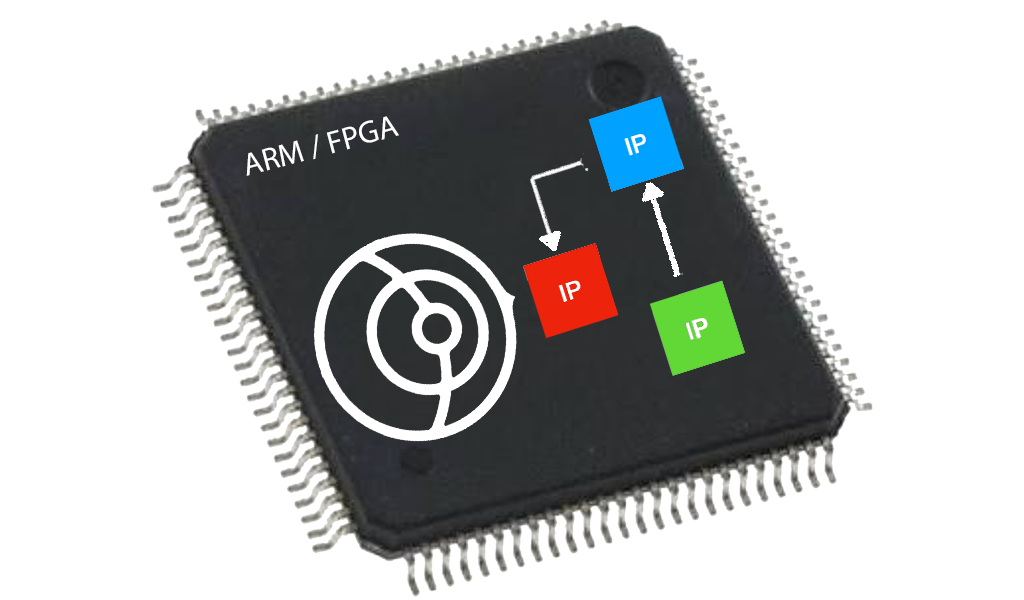
- The USRP family features a modular architecture with interchangeable daughterboard modules that serve as the RF front end. In the case of using a USRP without an embedded transceiver, you will need a daughterboard allowing the reception of signals around 1.5 GHz. That is: DBSRX2, WBX, SBX, CBX, and UBX daughterboards can work for you. You will not need a daughterboard if you are using USRP B200, B210, or E310, which ship an Analog Devices AD9361 RFIC as an integrated wideband transceiver.
| Daughterboard | Frequency coverage | Analog bandwidth | RX gain |
|---|---|---|---|
| WBX-120 | 50 MHz - 2.2 GHz | 120 MHz | \(0\) to \(31.5\) dB |
| SBX-120 | 400 MHz - 4.4 GHz | 120 MHz | \(0\) to \(31.5\) dB |
| CBX-120 | 1.2 GHz - 6 GHz | 120 MHz | \(0\) to \(31.5\) dB |
| UBX-160 | 10 MHz - 2.2 GHz | 160 MHz | \(0\) to \(31.5\) dB |
| WBX | 50 MHz - 2.2 GHz | 40 MHz | \(0\) to \(31.5\) dB |
| SBX | 400 MHz - 4.4 GHz | 40 MHz | \(0\) to \(31.5\) dB |
| CBX | 1.2 GHz - 6 GHz | 40 MHz | \(0\) to \(31.5\) dB |
| UBX-40 | 10 MHz - 6 GHz | 40 MHz | \(0\) to \(31.5\) dB |
| DBSRX2 | 800 MHz - 2.3 GHz | Configurable: 8 MHz to 80 MHz | GC1 from \(0\) to \(73\) dB, and BBC from \(0\) to \(15\) dB |
Daugtherboards allowing GNSS signal reception. Note that WBX-120, CBX-120 and SBX-120 daughterboards were designed to work with USRP X300/X310 and any future products with sufficient ADC/DAC sample rates. These boards are not compatible with devices that incorporate lower rate ADC/DAC below 200 MS/s. Source: Ettus Research Knowledge Base.
- A computer connected to the USRP and with GNSS-SDR installed.
Setting up the front-end
The first thing to do is to install a suitable daughterboard into the USRP. As
an example, you can check Ettus Research’s detailed step-by-step guide to
install a daughterboard into the USRP
N200/N210.
In USRPs with two receiving slots, please check in which one you are inserting
the daughterboard (they are usually labeled as “RX A” and “RX B”). This is
something that you will need to specify in the configuration file (via the
subdevice parameter, see below).
Then, you will need to feed your GNSS active antenna.
Important: Never apply more than -15 dBm of power into any RF input.
In the case of using a DBSRX2 daughterboard, you will need to adjust the J101 jumper in order to feed the antenna.
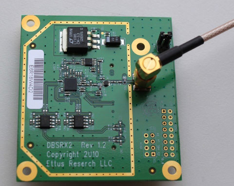 DBSRX2 daughterboard. The J101 jumper in the upper right corner allows the
injection of current towards the antenna. Source: Radio
Adventures.
DBSRX2 daughterboard. The J101 jumper in the upper right corner allows the
injection of current towards the antenna. Source: Radio
Adventures.
If this feature is not available (e.g., WBX daughterboards), you will need a bias-T between the USRP and the antenna, and to connect it to a power source delivering the voltage required by your antenna (usually, 3 V or 5 V).
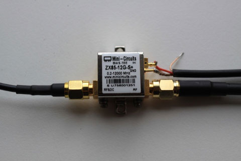 Bias-T allowing the injection of DC voltage to the antenna. Source: Radio Adventures .
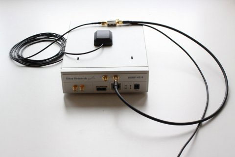 USRP N210 with the bias-T and the GPS antenna. Source: Radio Adventures.
Depending on the specific USRP model you are using, the connection to the host computer in charge of the execution of the software receiver can be through USB (2.0 or 3.0) or Ethernet (1 GigE or 10 GigE). Once connected, every USRP device has several ways of identifying it on the host system:
| Identifier | Key | Notes | Example |
|---|---|---|---|
| Serial # | serial |
globally unique identifier | 12345678 |
| IP Address | addr |
unique identifier on a network | 192.168.10.2 |
| Type | type |
hardware series identifier | usrp1, usrp2, b200, x300, … |
| Name | name |
optional user-set identifier | lab1_usrp3 |
Common device identifiers. Source: Identifying USRP Devices.
Devices attached to your system can be discovered using the uhd_find_devices
program. This program scans your system for supported devices and prints out an
enumerated list of discovered devices and their addresses. If you type
uhd_find_devices --help in a terminal, you should see something similar to
this:
$ uhd_find_devices --help
linux; GNU C++ version 4.9.2; Boost_105400; UHD_003.010.git-0-2d68f228

UHD Find Devices Allowed options:
  --help                help message
  --args arg            device address args
Then, you can search your USRP in a specific IP address:
$ uhd_find_devices --args addr=192.168.50.2
linux; GNU C++ version 4.9.2; Boost_105400; UHD_003.010.git-0-2d68f228

--------------------------------------------------
-- UHD Device 0
--------------------------------------------------
Device Address:
    type: x300
    addr: 192.168.50.2
    fpga: HGS
    name:
    serial: F5CA38
    product: X300
or by typing:
$ uhd_find_devices --args type=usrp1
This is a good way to check if the USRP is correctly connected to your computer. After this check, we can proceed to configure the software receiver. The USRP Hardware Driver and USRP Manual provides more information about the configuration and usage of those devices.
Setting up the software receiver
Copy the configuration below into your favorite plain text editor and save it
with a name such as my_GPS_receiver.conf in your working directory.
[GNSS-SDR]

;######### GLOBAL OPTIONS ##################
GNSS-SDR.internal_fs_sps=4000000

;######### SIGNAL_SOURCE CONFIG ############
SignalSource.implementation=UHD_Signal_Source
SignalSource.device_address=192.168.50.2 ; <- PUT THE IP ADDRESS OF YOUR USRP HERE
                                         ;    OR LEAVE IT EMPTY FOR USB
SignalSource.item_type=cshort
SignalSource.sampling_frequency=4000000
SignalSource.freq=1575420000
SignalSource.gain=40
SignalSource.subdevice=A:0  ; <- Can be A:0 or B:0
SignalSource.samples=0

;######### SIGNAL_CONDITIONER CONFIG ############
SignalConditioner.implementation=Signal_Conditioner

;######### DATA_TYPE_ADAPTER CONFIG ############
DataTypeAdapter.implementation=Pass_Through
DataTypeAdapter.item_type=cshort

;######### INPUT_FILTER CONFIG ############
InputFilter.implementation=Fir_Filter
InputFilter.input_item_type=cshort
InputFilter.output_item_type=gr_complex
InputFilter.taps_item_type=float
InputFilter.number_of_taps=11
InputFilter.number_of_bands=2

InputFilter.band1_begin=0.0
InputFilter.band1_end=0.48
InputFilter.band2_begin=0.52
InputFilter.band2_end=1.0

InputFilter.ampl1_begin=1.0
InputFilter.ampl1_end=1.0
InputFilter.ampl2_begin=0.0
InputFilter.ampl2_end=0.0

InputFilter.band1_error=1.0
InputFilter.band2_error=1.0

InputFilter.filter_type=bandpass
InputFilter.grid_density=16
InputFilter.sampling_frequency=4000000
InputFilter.IF=0

;######### RESAMPLER CONFIG ############
Resampler.implementation=Pass_Through

;######### CHANNELS GLOBAL CONFIG ############
Channels_1C.count=8
Channels.in_acquisition=1

;######### ACQUISITION GLOBAL CONFIG ############
Acquisition_1C.implementation=GPS_L1_CA_PCPS_Acquisition
Acquisition_1C.item_type=gr_complex
Acquisition_1C.coherent_integration_time_ms=1
Acquisition_1C.pfa=0.01
Acquisition_1C.doppler_max=5000
Acquisition_1C.doppler_step=250
Acquisition_1C.max_dwells=1
Acquisition_1C.dump=false
Acquisition_1C.dump_filename=./acq_dump.dat

;######### TRACKING GLOBAL CONFIG ############
Tracking_1C.implementation=GPS_L1_CA_DLL_PLL_Tracking
Tracking_1C.item_type=gr_complex
Tracking_1C.extend_correlation_symbols=10
Tracking_1C.early_late_space_chips=0.5
Tracking_1C.early_late_space_narrow_chips=0.15
Tracking_1C.pll_bw_hz=40
Tracking_1C.dll_bw_hz=2.0
Tracking_1C.pll_bw_narrow_hz=5.0
Tracking_1C.dll_bw_narrow_hz=1.50
Tracking_1C.fll_bw_hz=10
Tracking_1C.enable_fll_pull_in=true
Tracking_1C.enable_fll_steady_state=false
Tracking_1C.dump=false
Tracking_1C.dump_filename=tracking_ch_

;######### TELEMETRY DECODER GPS CONFIG ############
TelemetryDecoder_1C.implementation=GPS_L1_CA_Telemetry_Decoder

;######### OBSERVABLES CONFIG ############
Observables.implementation=Hybrid_Observables

;######### PVT CONFIG ############
PVT.implementation=RTKLIB_PVT
PVT.positioning_mode=Single
PVT.output_rate_ms=100
PVT.display_rate_ms=500
PVT.iono_model=Broadcast
PVT.trop_model=Saastamoinen
PVT.flag_rtcm_server=true
PVT.flag_rtcm_tty_port=false
PVT.rtcm_dump_devname=/dev/pts/1
PVT.rtcm_tcp_port=2101
PVT.rtcm_MT1019_rate_ms=5000
PVT.rtcm_MT1077_rate_ms=1000
PVT.rinex_version=2
You will need to adjust the values for at least two parameters:
- Check that
SignalSource.device_addresspoints to the actual IP address of your USRP, if you are connected through Ethernet, or leave it empty for USB. - Check that
SignalSource.subdeviceis set to the receiving slot in which you actually inserted your daughterboard with the antenna. In USRPs with only one receiving slot, leave it asA:0. Please check more details on how to specify the subdevice.
The Signal Processing Blocks documentation provides definitions and more details about the configuration parameters.
Run it!
Once the hardware and the software configurations are ready, go to your favorite
working directory where the file my_GPS_receiver.conf was stored and invoke
the software receiver with this particular configuration:
$ gnss-sdr --config_file=./my_GPS_receiver.conf
You should see something similar to:
$ gnss-sdr --config_file=./my_GPS_receiver.conf
Initializing GNSS-SDR v0.0.18 ... Please wait.
Logging will be done at "/tmp"
Use gnss-sdr --log_dir=/path/to/log to change that.
-- X300 initialization sequence...
-- Determining maximum frame size... 8000 bytes.
-- Setup basic communication...
-- Loading values from EEPROM...
-- Setup RF frontend clocking...
-- Radio 1x clock:200
-- Initialize Radio0 control...
-- Performing register loopback test... pass
-- Initialize Radio1 control...
-- Performing register loopback test... pass
Sampling Rate for the USRP device: 4000000.000000 [sps]...
UHD RF CHANNEL #0 SETTINGS
Actual USRP center freq.: 1575420000.010133 [Hz]...
PLL Frequency tune error 0.010133 [Hz]...
Actual daughterboard gain set to: 37.500000 dB...
Setting RF bandpass filter bandwidth to: 2000000.000000 [Hz]...
Check for front-end LO: locked ... is Locked
Using Volk machine: avx2_64_mmx
Starting a TCP Server on port 2101
The TCP Server is up and running. Accepting connections ...
...
Of course, file my_GPS_receiver.conf can be wherever (--config-file accepts
both relative and absolute paths), and the data displayed at the terminal output
might vary according to your setup.
Then, after some seconds detecting GPS signals and decoding some frames of their navigation messages (at least, subframes 1, 2, and 3 from four satellites)…
...
Current input signal time = 49 [s]
Current input signal time = 50 [s]
Current input signal time = 51 [s]
Current input signal time = 52 [s]
NAV Message: received subframe 1 from satellite GPS PRN 27 (Block IIF)
NAV Message: received subframe 1 from satellite GPS PRN 10 (Block IIF)
NAV Message: received subframe 1 from satellite GPS PRN 08 (Block IIF)
NAV Message: received subframe 1 from satellite GPS PRN 16 (Block IIR)
NAV Message: received subframe 1 from satellite GPS PRN 18 (Block IIR)
Current input signal time = 53 [s]
Current input signal time = 54 [s]
Current input signal time = 55 [s]
Current input signal time = 56 [s]
Current input signal time = 57 [s]
Current input signal time = 58 [s]
NAV Message: received subframe 2 from satellite GPS PRN 27 (Block IIF)
NAV Message: received subframe 2 from satellite GPS PRN 10 (Block IIF)
NAV Message: received subframe 2 from satellite GPS PRN 08 (Block IIF)
NAV Message: received subframe 2 from satellite GPS PRN 16 (Block IIR)
NAV Message: received subframe 2 from satellite GPS PRN 18 (Block IIR)
Current input signal time = 59 [s]
Current input signal time = 60 [s]
Current input signal time = 61 [s]
Current input signal time = 62 [s]
Current input signal time = 63 [s]
Current input signal time = 64 [s]
NAV Message: received subframe 3 from satellite GPS PRN 27 (Block IIF)
NAV Message: received subframe 3 from satellite GPS PRN 10 (Block IIF)
NAV Message: received subframe 3 from satellite GPS PRN 08 (Block IIF)
NAV Message: received subframe 3 from satellite GPS PRN 16 (Block IIR)
NAV Message: received subframe 3 from satellite GPS PRN 18 (Block IIR)
Current input signal time = 65 [s]
Position at 2016-Aug-11 14:23:19 UTC is Lat = 41.2751 [deg], Long = 1.98765 [deg], Height= 68.9893 [m]
Position at 2016-Aug-11 14:23:19 UTC is Lat = 41.2751 [deg], Long = 1.98765 [deg], Height= 72.1068 [m]
Current input signal time = 66 [s]
Position at 2016-Aug-11 14:23:20 UTC is Lat = 41.2751 [deg], Long = 1.9877 [deg], Height= 67.0216 [m]
Position at 2016-Aug-11 14:23:20 UTC is Lat = 41.2751 [deg], Long = 1.9877 [deg], Height= 84.7445 [m]
Current input signal time = 67 [s]
Position at 2016-Aug-11 14:23:21 UTC is Lat = 41.2751 [deg], Long = 1.98771 [deg], Height= 70.0031 [m]
Position at 2016-Aug-11 14:23:21 UTC is Lat = 41.2751 [deg], Long = 1.98767 [deg], Height= 63.1242 [m]
Current input signal time = 68 [s]
...
If you see something similar to this… Yay! You are getting real-time position fixes with your open-source software-defined GPS receiver!
Important: In order to get well-formatted GeoJSON, KML, and RINEX files,
always terminate gnss-sdr execution by pressing key ‘q’ and then key
‘ENTER’. Those files will be automatically deleted if no position fix has
been obtained during the execution of the software receiver.
Always stop the execution of GNSS-SDR by pressing key ‘q’ and then key
‘ENTER’ (not at the same time, first ‘q’ and then ‘ENTER’):
...
Position at 2016-Aug-11 14:23:31 UTC is Lat = 41.2751 [deg], Long = 1.98762 [deg], Height= 58.1987 [m]
q
Quit keystroke order received, stopping GNSS-SDR !!
Stopping GNSS-SDR, please wait!
Total GNSS-SDR run time 78.3891 [seconds]
GNSS-SDR program ended.
Stopping TCP Server on port 2101
$
Now you can examine the files created in your working folder.
If something goes wrong
-
Check out that the GNSS antenna is actually fed and that it is placed in a location with good sky visibility.
-
Check out Ettus Research’s getting starting guide for your particular hardware configuration.
-
Watch out for overflows! Maybe your host computer is not able to sustain the required computational load for this particular implementation.
Overflow warnings:
When receiving, the USRP device produces samples at a constant rate. Overflows
occur when the host computer does not consume data fast enough. When UHD
software detects the overflow, it prints an “O” or “D” to the standard
terminal output and pushes an inline message packet into the receive stream.
- Network-based devices (e.g., USRP N2xx, X3xx): The host does not
back-pressure the receive stream. When the kernel’s socket buffer becomes
full, it will drop subsequent packets. UHD software detects the overflow as a
discontinuity in the packet’s sequence numbers and pushes an inline message
packet into the receive stream. In this case, the character
Dis printed to the standard terminal output as an indication. - Other devices (e.g., USRP 1, B2xx): The host back-pressures the
receive stream. Therefore, overflows always occur in the device itself. When
the device’s internal buffers become full, streaming is shut off, and an
inline message packet is sent to the host. In this case, the character “
O” is printed to the standard terminal output as an indication. If the device was in continuous streaming mode, the UHD software will automatically restart streaming when the buffer has space again.
- Play with configuration parameters!
GPS L1 C/A receiver using a HackRF One
HackRF One from Great Scott Gadgets is an open-source Software Defined Radio peripheral capable of reception of radio signals from 1 MHz to 6 GHz, and thus is well suited for GNSS applications. If features:
- Up to 20 million samples per second.
- 8-bit quadrature samples (8-bit I and 8-bit Q).
- Software-configurable RX gain and baseband filter.
- Software-controlled antenna port power (50 mA at 3.3 V).
- SMA female antenna connector.
- SMA female clock input and output for synchronization.
- Hi-Speed USB 2.0.
- USB-powered.
 HackRF One.
For more information, check out the HackRF documentation.
Required equipment
In order to get real-time position fixes, you will need:
- An active GPS antenna. Most models will fit, just check that you can plug it to the HackRF’s SMA-female connector, and that 50 mA at 3.3 V is an adequate feeding.
- A HackRF One.
- A stable clock: the oscillator shipped with the HackRF is not good enough for GNSS signal processing. You will need a frequency stability of 1 ppm or better.
- A computer connected to the HackRF One and with GNSS-SDR installed.
This device requires the use of the Osmosdr_Signal_Source implementation. If you installed GNSS-SDR from a software
package, this implementation is already available. But if you are building
GNSS-SDR from the source code, you will need the required software dependencies
(the gr-osmosdr component of GNU Radio) and configure the building with the
following flag:
$ cmake -DENABLE_OSMOSDR=ON ../
and then build and install the software:
$ make
$ sudo make install
For more information, check out the tutorial about GNSS-SDR options at building time.
Setting up the front-end
Once the software is ready, connect your HackRF to your computer, and connect
the active antenna. In order to activate the antenna feeding, the configuration
file must use the Osmosdr_Signal_Source implementation and include the following line:
SignalSource.osmosdr_args=hackrf,bias=1
You will need to provide an external clock source to the HackRF with a frequency stability of 1 ppm or better (so a 10 MHz oscillator will vary by 10 Hz).
Setting up the software receiver
A possible configuration file could be:
[GNSS-SDR]

;######### GLOBAL OPTIONS ##################
GNSS-SDR.internal_fs_sps=2000000

;######### SIGNAL_SOURCE CONFIG ############
SignalSource.implementation=Osmosdr_Signal_Source
SignalSource.item_type=gr_complex
SignalSource.sampling_frequency=2000000
SignalSource.freq=1575420000
SignalSource.gain=40
SignalSource.rf_gain=40
SignalSource.if_gain=30
SignalSource.AGC_enabled=false
SignalSource.samples=0
SignalSource.repeat=false
;# Next line enables the internal HackRF One bias (3.3 VDC)
SignalSource.osmosdr_args=hackrf,bias=1
SignalSource.enable_throttle_control=false
SignalSource.dump=false
SignalSource.dump_filename=./signal_source.dat

;######### SIGNAL_CONDITIONER CONFIG ############
SignalConditioner.implementation=Signal_Conditioner

;######### DATA_TYPE_ADAPTER CONFIG ############
DataTypeAdapter.implementation=Pass_Through

;######### INPUT_FILTER CONFIG ############
InputFilter.implementation=Freq_Xlating_Fir_Filter
InputFilter.decimation_factor=1
InputFilter.input_item_type=gr_complex
InputFilter.output_item_type=gr_complex
InputFilter.taps_item_type=float
InputFilter.number_of_taps=5
InputFilter.number_of_bands=2
InputFilter.band1_begin=0.0
InputFilter.band1_end=0.85
InputFilter.band2_begin=0.9
InputFilter.band2_end=1.0
InputFilter.ampl1_begin=1.0
InputFilter.ampl1_end=1.0
InputFilter.ampl2_begin=0.0
InputFilter.ampl2_end=0.0
InputFilter.band1_error=1.0
InputFilter.band2_error=1.0
InputFilter.filter_type=bandpass
InputFilter.grid_density=16
InputFilter.dump=false
InputFilter.dump_filename=../data/input_filter.dat

;######### RESAMPLER CONFIG ############
Resampler.implementation=Pass_Through

;######### CHANNELS GLOBAL CONFIG ############
Channels_1C.count=8
Channels.in_acquisition=1

;######### ACQUISITION GLOBAL CONFIG ############
Acquisition_1C.implementation=GPS_L1_CA_PCPS_Acquisition
Acquisition_1C.item_type=gr_complex
Acquisition_1C.coherent_integration_time_ms=1
Acquisition_1C.pfa=0.01
Acquisition_1C.doppler_max=5000
Acquisition_1C.doppler_step=250
Acquisition_1C.max_dwells=1
Acquisition_1C.dump=false
Acquisition_1C.dump_filename=./acq_dump.dat

;######### TRACKING GLOBAL CONFIG ############
Tracking_1C.implementation=GPS_L1_CA_DLL_PLL_Tracking
Tracking_1C.item_type=gr_complex
Tracking_1C.extend_correlation_symbols=10
Tracking_1C.early_late_space_chips=0.5
Tracking_1C.early_late_space_narrow_chips=0.15
Tracking_1C.pll_bw_hz=40
Tracking_1C.dll_bw_hz=2.0
Tracking_1C.pll_bw_narrow_hz=5.0
Tracking_1C.dll_bw_narrow_hz=1.50
Tracking_1C.fll_bw_hz=10
Tracking_1C.enable_fll_pull_in=true
Tracking_1C.enable_fll_steady_state=false
Tracking_1C.dump=false
Tracking_1C.dump_filename=tracking_ch_

;######### TELEMETRY DECODER GPS CONFIG ############
TelemetryDecoder_1C.implementation=GPS_L1_CA_Telemetry_Decoder
TelemetryDecoder_1C.dump=false

;######### OBSERVABLES CONFIG ############
Observables.implementation=Hybrid_Observables
Observables.dump=false
Observables.dump_filename=./observables.dat

;######### PVT CONFIG ############
PVT.implementation=RTKLIB_PVT
PVT.positioning_mode=Single
PVT.output_rate_ms=100
PVT.display_rate_ms=500
PVT.iono_model=Broadcast
PVT.trop_model=Saastamoinen
PVT.flag_rtcm_server=true
PVT.flag_rtcm_tty_port=false
PVT.rtcm_dump_devname=/dev/pts/1
PVT.rtcm_tcp_port=2101
PVT.rtcm_MT1019_rate_ms=5000
PVT.rtcm_MT1077_rate_ms=1000
PVT.rinex_version=2
Copy and paste this configuration in your favorite plain text editor and save it
as, for instance, hackrf_GPS_L1.conf.
Once the hardware and the software configurations are ready, go to your favorite
working directory where the file hackrf_GPS_L1.conf was stored and invoke the
software receiver with this particular configuration:
$ gnss-sdr --config_file=./hackrf_GPS_L1.conf
You should see something similar to the example above.
HackRF and GNSS-SDR in action
The process of setting up a GPS receiver with a HackRF and GNSS-SDR is nicely described in the following video by Don Kelly, including hardware aspects and the usage of the gnss-sdr-monitor graphic interface.